Optical phase detecting high precision silicon microelectromechanical gyroscope

A silicon micro-electromechanical gyro, high-precision technology, applied in gyroscope/steering sensing equipment, using optical devices, gyro effect for speed measurement, etc., can solve the problem of large noise in the output signal of the micro-electromechanical gyroscope, difficulty in improving accuracy and sensitivity, and drift Poor stability and other issues, to achieve the effect of improving the dynamic response range, improving detection sensitivity and readout accuracy, and low cost

Inactive Publication Date: 2009-08-19
CHONGQING UNIV
View PDF0 Cites 10 Cited by
  • Summary
  • Abstract
  • Description
  • Claims
  • Application Information

AI Technical Summary

Problems solved by technology

[0005] However, the capacitive detection method usually adopted by MEMS gyroscopes has a very small capacitance change of up to 10 -18 F, so the accuracy and sensitivity are difficult to improve, and the accuracy is far inferior to laser and fiber optic gyroscopes, so it can only be applied to low-end angle measurement systems
At the same time, due to the existence of parasitic capacitance, the noise of the output signal of the MEMS gyro is relatively large, and the drift stability is poor.

Method used


Image

  • Optical phase detecting high precision silicon microelectromechanical gyroscope
  • Optical phase detecting high precision silicon microelectromechanical gyroscope
  • Optical phase detecting high precision silicon microelectromechanical gyroscope

Examples


Embodiment Construction

[0018] The present invention is described in detail below in conjunction with embodiment.

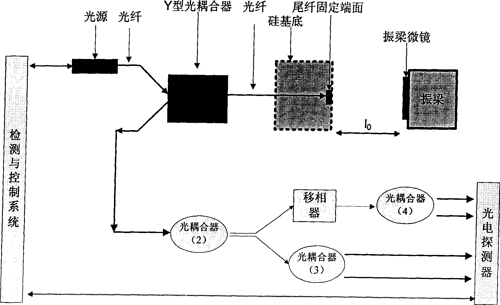
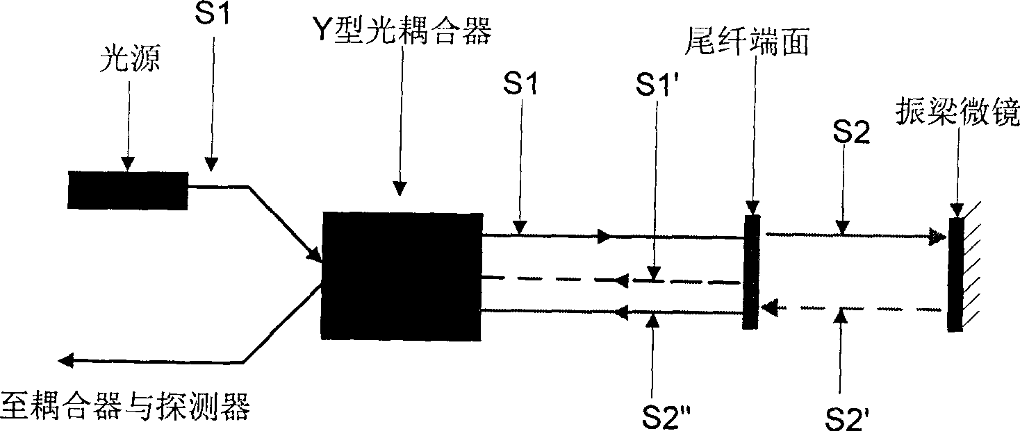
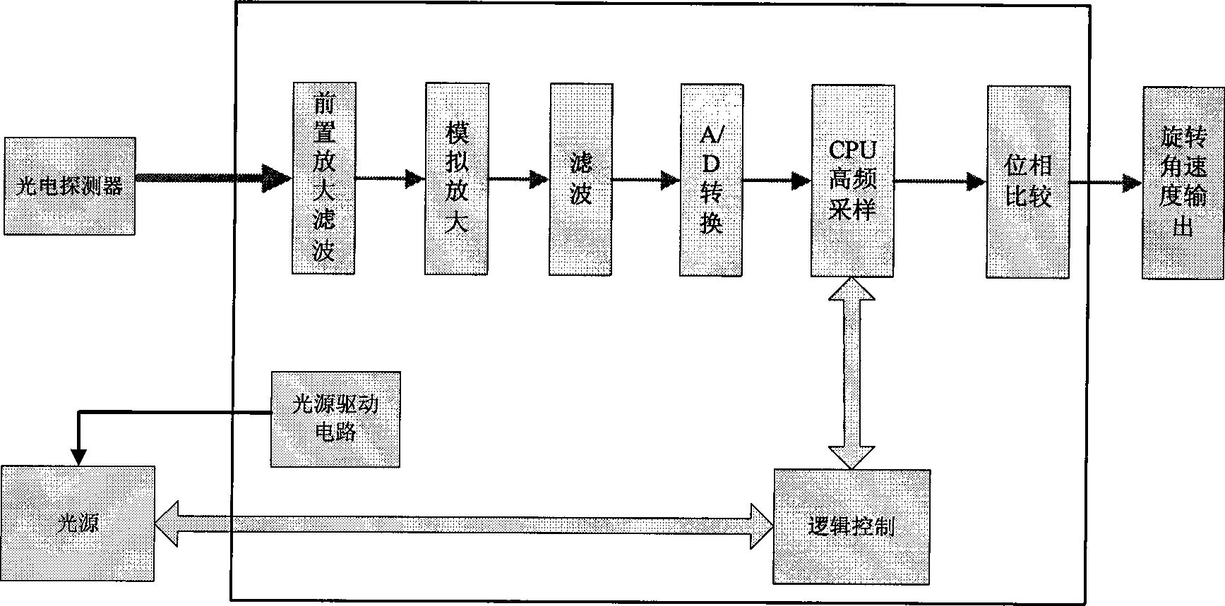
[0019] The structure of the high-precision silicon micro-electromechanical gyroscope for optical phase detection of the present invention is as follows: figure 1 As shown, it includes a light source formed by a semiconductor laser (LD) with a pigtail, a Y-type optical coupler, a second, a third, a fourth optical coupler, a phase shifter, a photodetector, a detection and control system and an oscillator Beam silicon MEMS gyro body, figure 1 Only the vibrating beam part of the vibrating beam silicon MEMS gyroscope body is shown in the figure to represent the gyroscope body. The tail fiber of the light source is fused with one fiber of the Y-type optical coupler, the other fiber of the Y-type optical coupler is fused with the input fiber of the second optical coupler, and the two output fibers of the second The input fiber of the phase shifter and the third optical coupler is fused, the ...


PUM


Abstract

The invention relates to a high precision silicon micro electronmechanical gyroscope of optical phase detection. Tail optical fiber of a light source and entering fiber of a photoelectric detector are respectively in heat sealing with one optical fiber of a Y-shaped optical coupler. A micro mirror is made on a vibration beam to be used for reflecting transmitted light passing through the tail optical fiber of the Y-shaped optical coupler. The photoelectric detector detects interference fringe formed by the confluence of the reflected light on the micromirror and the reflected light on the end face of the tail optical fiber of the Y-shaped optical coupler by the Y-shaped optical coupler. The photoelectric detector is connected with a detection and control system. The invention adopts optical interference principle and uses an optical phase measurement method to measure the infinitesimal displacement of a vibration mass block, thus improving the detection sensitivity and reading accuracy of the gyroscope. The gyroscope is characterized by small volume, light weight, high resolution, low drift, short response time and high reading accuracy, improves dynamic response range and detection accuracy, is beneficial to the implementation of digital filter and signal transmission processing simultaneously and improves the anti-interference capacity of the system.

Description

technical field [0001] The invention relates to a device for measuring rotational angular velocity, in particular to a high-precision silicon micro-electromechanical gyroscope using optical phase detection, which combines optical fiber Michelson interference technology on the basis of traditional silicon micro-electromechanical gyroscopes, and integrates optical and micro-electromechanical systems ( MEMS), precision machinery and electronic technology in one sensor, can upgrade the medium and low precision MEMS gyroscope to medium and high precision MEMS gyroscope. Background technique [0002] The principle of the gyroscope is: the direction pointed by the rotation axis of a rotating object will not change when it is not affected by external forces, and then read the direction indicated by the axis in a variety of ways, which is to maintain relative tracking in dynamic State of the precision angle, angular velocity sensor. Because the gyroscope can carry out independent me...

Claims


Application Information

Patent Timeline
Patent Type & Authority Applications(China)
IPC IPC(8): G01C19/56G01B11/02G01C19/5656
Inventor 任春华潘英俊魏彪熊凝香
Owner CHONGQING UNIV
Why Eureka
Try Eureka