Circuit for measuring outburst mode optical signal power

A power measurement, burst mode technology, applied in electrical components, electromagnetic wave transmission systems, selection devices for multiplexing systems, etc., can solve the problem that single-stage gain discharge circuits are difficult to meet a wide range of measurement requirements, response time Long time (several microseconds to hundreds of microseconds, difficult to work stably, etc., to achieve the effect of increasing gain and driving capability, strong common mode noise suppression capability, and enhanced system stability

Inactive Publication Date: 2009-08-19
SUPERXON (CHENGDU) TECH LTD
View PDF0 Cites 36 Cited by
  • Summary
  • Abstract
  • Description
  • Claims
  • Application Information

AI Technical Summary

Problems solved by technology

[0004] In the existing technology, some methods of converting the photocurrent of the photodetector into a voltage signal and then using a comparator to set the threshold to generate a trigger condition for burst optical power input are used to perform burst sampling, but in order to ensure at least The dynamic range of the input optical signal power is above 30dB. When the full scale of the analog-to-digital conversion is 2.5V, when the system is near the sensitivity, the voltage value corresponding to the optical power is only 2.5mV. At this time, the threshold level set by the comparator has already entered noise threshold, making it difficult for the system to work stably
At the same time, the discharge circuit with single-stage gain is also difficult to meet the measurement requirements of a wide range
There is also a technical scheme of using a current-voltage type logarithmic amplifier for burst sampling, but due to the long response time of the current-voltage type logarithmic amplifier (several microseconds to hundreds of microseconds), even with a dummy load The method is also difficult to reach hundreds of nanoseconds, and it is difficult to meet the actual test requirements. Therefore, it is still difficult to effectively solve the power measurement of burst optical signals in the current technical solutions.

Method used


Image

  • Circuit for measuring outburst mode optical signal power
  • Circuit for measuring outburst mode optical signal power
  • Circuit for measuring outburst mode optical signal power

Examples


Embodiment Construction

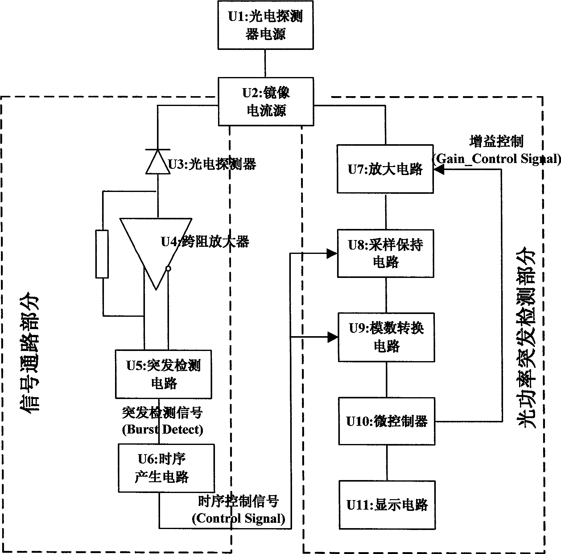
[0019] figure 1 An embodiment of the signal power burst detection circuit of the present invention is described, wherein:

[0020] The photodetector power supply U1 provides voltage bias for the photodetector (U3);

[0021] The mirror current source U2 generates a mirror current in proportion to the average photocurrent of the photodetector U3.

[0022] The amplifying circuit U7 converts the mirror current into a voltage signal, and the voltage signal is proportional to the power of the optical signal. The amplifying circuit has multi-stage gains, and different gain sizes are selected under the control of the gain control signal (Gain_ControlSignal) of the microprocessor.

[0023] The transimpedance amplifier U3 is connected with the photodetector U3, and converts the photocurrent into a differential voltage signal;

[0024] A burst detection circuit U5, configured to receive the voltage signal of the above-mentioned transimpedance amplifier, and generate a burst detection...


PUM


Abstract

The invention discloses a burst mode optical signal power measuring circuit which comprises a photoelectric detector power supply, a mirror image current source and a subsequent circuit. The subsequent circuit is divided into a signal passage part and an optical power burst detecting part by the mirror image current source, wherein, in the signal passage part, optical current generates a burst detection signal by the photoelectric detector via a trans-impedence amplifier and a burst detection circuit, and the burst detection signal is used for triggering a time sequence generation circuit to generate a control time sequence for maintaining sampling and carrying out digital-to-analog conversion; in the optical power burst detection part, an amplifying circuit converts the mirror image current into a voltage signal; therefore, a sampling maintaining circuit and a digital-to-analog conversion circuit which are connected with the time sequence generation circuit can finish the burst detection of optical power under the control of the control time sequence. The burst mode optical signal power measuring circuit generates the mirror image current forming a proportion with the average optical current of the photoelectric detector by the mirror image current source, realizes the detection to the burst mode optical power under the control of the control time sequence, and can measure burst optical signal power with the length of hundreds of nanoseconds.

Description

technical field [0001] The invention relates to a circuit for measuring optical input power in the technical field of optical communication, and relates to a power measurement circuit of a burst mode optical signal of a point-to-multipoint optical network such as a passive optical network. technical background [0002] The construction of access network based on passive optical network technology is a bright spot in the optical communication industry in recent years. Passive optical network is a point-to-multipoint system, an optical line terminal (OLT) and multiple optical network terminals (ONT) Through the tree-shaped optical fiber link connection, not only part of the optical fiber link resources are shared, but also the cost of the optical line terminal (OLT) is shared, and the cost of the optical line terminal (OLT) does not require active devices in the middle, which greatly reduces the cost of network construction. and maintenance costs. [0003] In the passive opti...

Claims


Application Information

Patent Timeline
Patent Type & Authority Applications(China)
IPC IPC(8): H04B10/08H04Q11/00H04B10/079
Inventor 姜先刚邹渊蒋小青
Owner SUPERXON (CHENGDU) TECH LTD
Why Eureka
Try Eureka