

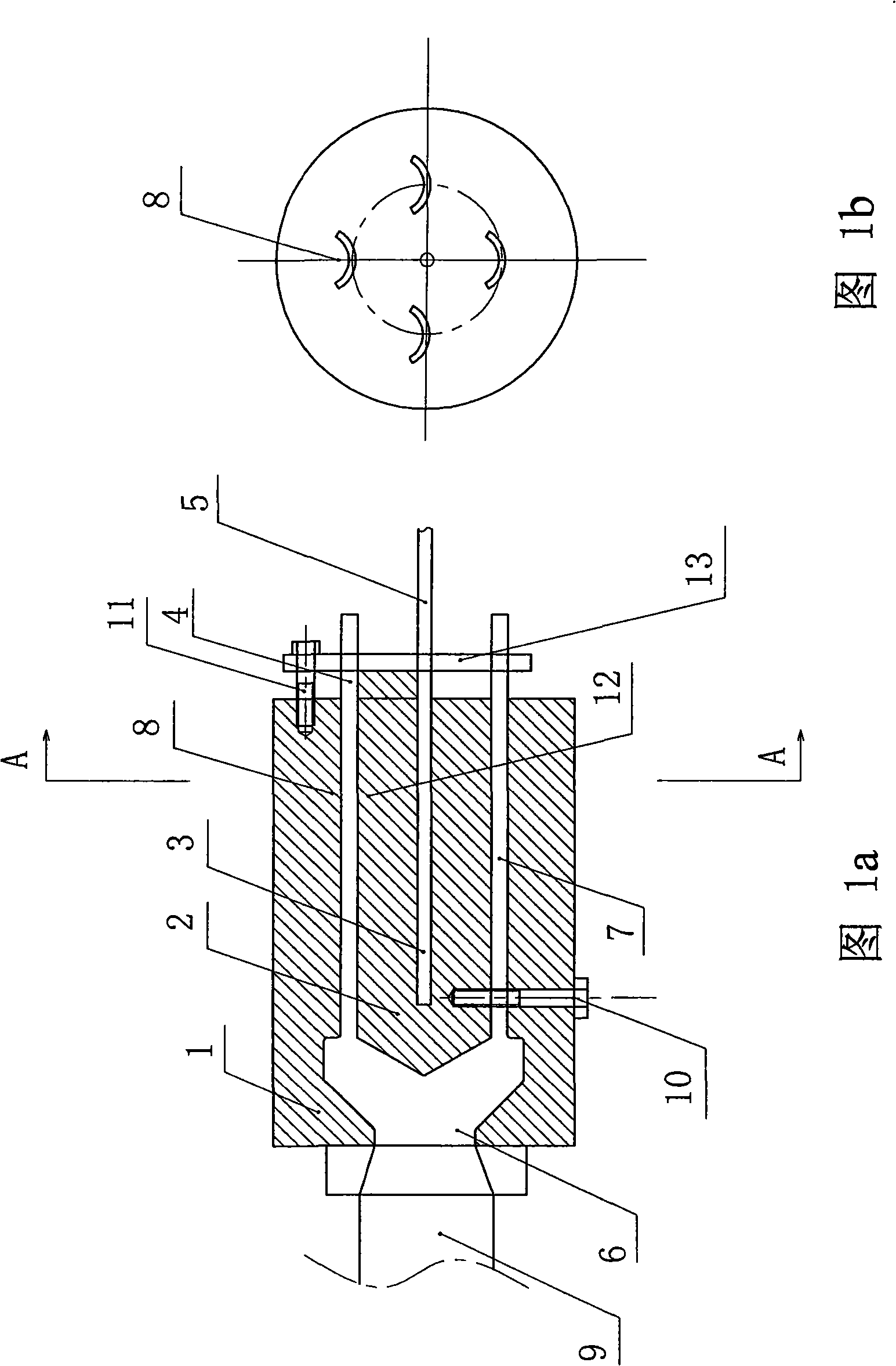
Flow channel device capable of extruding out a plurality of magnets once for extruding machine and preparation method using same
An extrusion molding machine and flow channel technology, applied in the direction of magnetism of inorganic materials, can solve the problems of uneven magnet density, uneven density, component segregation, etc., easy to achieve size and shape tolerance, good central symmetry, density easy consistent effect
- Summary
- Abstract
- Description
- Claims
- Application Information
AI Technical Summary
Problems solved by technology
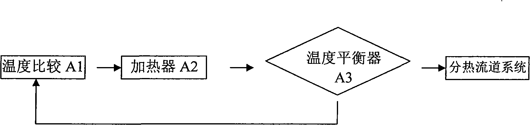
Method used
Image

Examples
Embodiment 1
[0091] The NdFeB magnetic powder used in the magnet accounts for 84 wt%, the ferrite magnetic powder accounts for 1 wt%, and the binder PPS accounts for 15 wt%. After uniform mixing and kneading, it is made into kneading powder. Using the extrusion flow channel device of the present invention, under the conditions of temperature, extrusion speed and extrusion pressure of each flow channel of the extrusion device shown in Table 2, one-time extrusion molding was performed to obtain multiple pieces of magnets.
[0092] Table 2
[0093] parts
Main hot runner 6
Sub-hot runner 7 front
(near main road)
Sub-hot runner 7 rear
(near exit)
Formed
magnet 4
temperature(°C)
310~320
290~300
250~260
≤135
Extrusion speed(mm / s)
3~4
5~6
5~6
5~6
Extrusion pressure (MPa)
≥10
≥8
≥7
-
[0094] The texture of each point of the obtained tile-shape...
Embodiment 2
[0097] The NdFeB magnetic powder used in the magnet accounts for 96 wt% of the total weight, and the polyamide resin accounts for 4 wt% of the total weight. After uniform mixing and kneading, it is made into kneading powder. Using the extrusion flow channel device of the present invention, under the conditions of temperature, extrusion speed and extrusion pressure of each flow channel of the extrusion device shown in Table 3, one-time extrusion molding was performed to obtain multiple pieces of magnets.
[0098] table 3
[0099] parts
Main hot runner 6
Sub-hot runner 7 front
(near main road)
Sub-hot runner 7 rear
(near exit)
Formed
magnet 4
temperature(°C)
240~243
220~230
135~145
≤135
Extrusion speed(mm / s)
2~3
4~5
4~5
4~5
Extrusion pressure (MPa)
≥10
≥9
≥6
-
[0100] The texture of each point of the obtained fan-shaped long bar magnet is un...
Embodiment 3
[0103] The NdFeB magnetic powder used in the magnet accounts for 22 wt%, the ferrite magnetic powder accounts for 70 wt%, and the polyamide resin accounts for 8.0 wt%. After uniform mixing and kneading, it is made into kneading powder. Using the extrusion flow channel device of the present invention, under the conditions of the temperature, extrusion speed and extrusion pressure of each flow channel of the extrusion device shown in Table 4, one-time extrusion molding was performed to obtain multiple pieces of magnets.
[0104] Table 4
[0105] parts
[0106] The texture of each point of the obtained ring-shaped magnet is uniform, so the magnetic performance is very uniform, and the size meets the requirements of the drawing. The obtained ring-shaped magnet is as follows Figure 5 As mentioned above, wherein, the outer diameter φ51=17.30±0.05mm, the inner diameter φ52=15.30±0.05mm, the roundness of the outer circular surface is 0.025mm, the coaxiality of the outer ci...
PUM
| Property | Measurement | Unit |
|---|---|---|
| density | aaaaa | aaaaa |
| magnetic energy product | aaaaa | aaaaa |
| magnetism | aaaaa | aaaaa |
Abstract
Description
Claims
Application Information