Mixed powder alloy with high melting point particles or fibers and low melting point particles as well as method for preparing same

A mixed powder, high melting point technology, applied in the field of powder metallurgy materials, can solve problems such as the collapse of porous particles and the interconnection of network fiber structures

Inactive Publication Date: 2009-09-02
王广武
View PDF2 Cites 13 Cited by
  • Summary
  • Abstract
  • Description
  • Claims
  • Application Information

AI Technical Summary

Problems solved by technology

3. Under heating conditions, use the flow characteristics of low melting point particles to melt into liquid, fill the gaps between unmelted high melting point porous particles or reticular fibers, and form a three-dimensional network of low melting point materials to wrap high melting point porous particles or reticular fiber structures , to solve the problem of the collapse of porous particles and the interconnection of network fiber structures

Method used


Image

  • Mixed powder alloy with high melting point particles or fibers and low melting point particles as well as method for preparing same
  • Mixed powder alloy with high melting point particles or fibers and low melting point particles as well as method for preparing same
  • Mixed powder alloy with high melting point particles or fibers and low melting point particles as well as method for preparing same

Examples


Embodiment 1

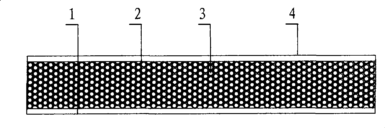
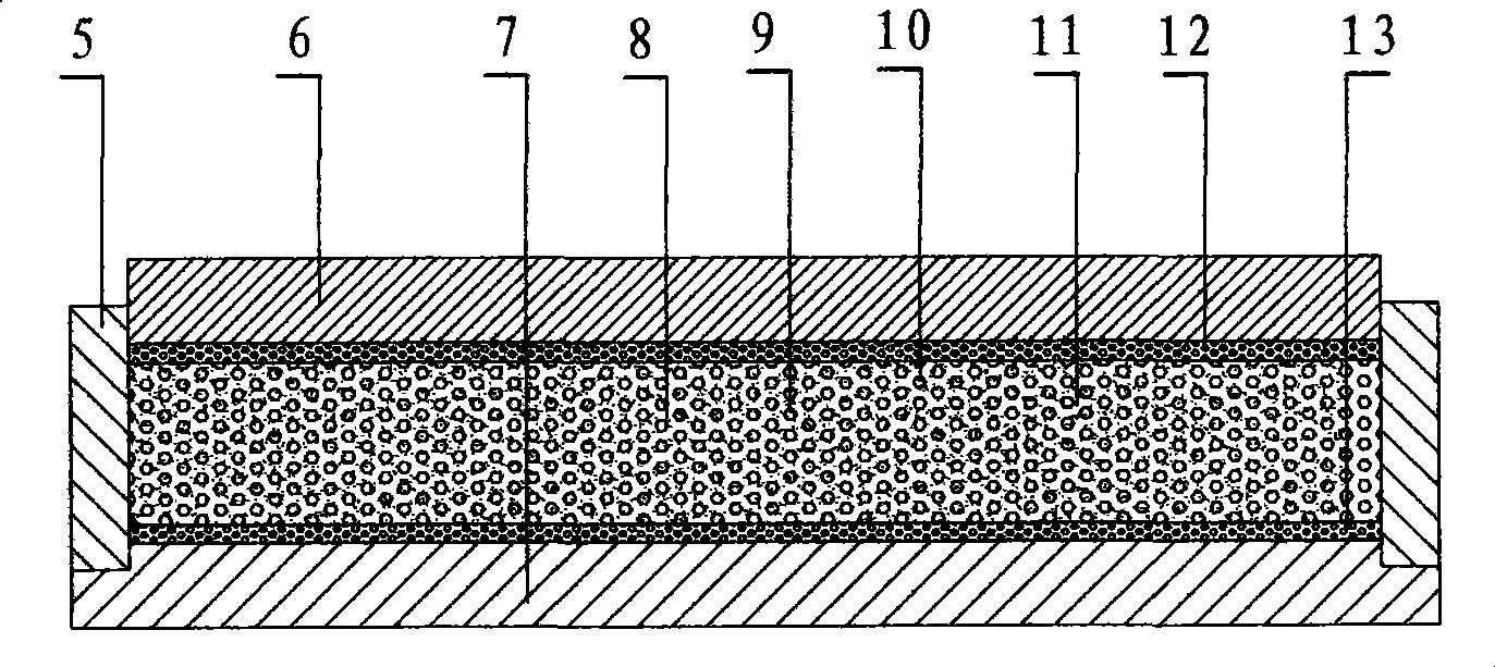
[0049] A structural diagram of a thermal insulation wallboard filled with expanded perlite particles figure 1 as shown, figure 2 It is the manufacturing structure diagram of the thermal insulation wallboard filled with expanded perlite particles, of which: 1 is the PVDF panel, 2 is the expanded perlite particle after filling, 3 is the PP resin mesh skeleton, 4 is the PP panel, 5 is the metal sleeve mold, 6 is Metal gland, 7 is the metal bottom plate, 8 is the mold cavity, 9 is expanded perlite particles, 10 is toluenesulfonamide (TSS or TSSC) foaming powder, 11 is the core PP resin particles, 12 is PP resin Particles, 13 are PVDF resin particles. The porous thermal insulation wallboard is composed of PVDF panel 1 and PP panel 4 and core PP porous resin network skeleton 3 wrapped with expanded perlite particles 4 .

[0050] The manufacturing process of the thermal insulation wallboard is as follows: the expanded perlite particles 9 are evenly mixed with 1% silane coupling ag...

Embodiment 2

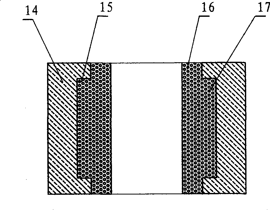
[0053] A copper-tin polyimide alloy bearing structure diagram as shown image 3 as shown, Figure 4 It is the flow chart of the manufacture of copper-tin polyimide particles, Figure 5 is the structural diagram of the manufacturing process of the copper-tin polyimide alloy bearing pad, in which: 14 is the steel jacket, its function is to keep the bearing with sufficient strength without deformation; The imide composite material is inlaid in the steel jacket groove to prevent the copper-tin polyimide composite material from falling off, 16 is the polyimide mesh skeleton, 17 is the copper-tin alloy particle, and the copper-tin alloy particle 17 is wrapped in polyimide In the mesh skeleton 16 pores, 18 is a polyimide particle, 19 is a heater, 20 is a mold base, 21 is a mold upper cover, 22 is a central axis, and 23 is a pressure ring of copper-tin-polyimide mixed particles. First, the coupling agent with a weight ratio of 1% of the CuSn particles is sprayed into the 2500-mesh C...

Embodiment 3

[0056] The manufacturing structure diagram of a corrosion-resistant propeller Figure 6 As shown, wherein: 24 is the metal propeller core, 25 is the positioning shaft under the propeller core, and 26 is TiO 2Particles, 27 are epoxy resin particles, 28 are carbon fibers or hybrid fibers, 29 are models, 30 are fixed sleeves, and 31 are vibrators. First, 5% TiO2 particles 26 are mixed with epoxy resin particles 27 and 10% carbon fibers or hybrid fibers to manufacture epoxy resin mixture particles containing TiO2 particles 26 and carbon fibers or hybrid fibers, and the metal propeller core 24 is placed on the model 29 Among them, the upper part is fixed with a fixed sleeve 30, and the lower part is fixed with the positioning shaft 25 under the propeller core, leaving a gap of 5-50mm between the model and the metal propeller core, and the epoxy resin mixed particles containing TiO2 and carbon fiber or hybrid fiber are placed along the model and Metal propeller core gap filling, wh...


PUM

PropertyMeasurementUnit
densityaaaaaaaaaa

Abstract

The invention relates to a mixed powder alloy with high melting point particles or fibers and low melting point particles, which comprises the high melting point particles or fibers made up of one material or various materials, the low melting point particles made up of one material or various materials, an auxiliary agent and a cast die, wherein the high melting point particles or the fibers and the low melting point particles are mixed together evenly and then are pressurized, heated and melted into a liquid state low melting point material which is filled into gaps of adjacent high melting point particles or the fibers so as to form an alloy structure which is formed by enwrapping the high melting point particles or the fibers by a three-dimensional netlike framework of the low melting point material, or a new alloy material which is formed on an interface by the three-dimensional netlike framework of the low melting point material and an enwrapped high melting point material.

Description

Field of invention: [0001] The invention relates to powder metallurgy materials. Background technique: [0002] Chinese patent ZL02158146.0 "Particle Alloy" discloses a particle alloy with iron and carbon as the main components. This invention presses the particle alloy containing Cu, Zn-St, and C into a cylinder by a pressure method, and does not involve the present invention. Preparation of alloys of high melting point particles or fibers and low melting point particles. [0003] Chinese patent ZL97100450.1 "Manufacturing Method of Granular Alloy Balls" adopts pressurization and sintering methods to manufacture granular alloy balls, and does not involve the preparation of high melting point particles or fibers and low melting point particle alloys proposed by the present invention. Invention content: [0004] The objectives of the present invention are: 1. Solve the problem of fusion molding of high-melting point particles or fibers and low-melting point particles. 2. ...

Claims


Application Information

Patent Timeline
Patent Type & Authority Applications(China)
IPC IPC(8): C22C1/08C22C49/00C22C47/12
Inventor 王广武
Owner 王广武
Why Eureka
Try Eureka