Plasma display panel manufacturing method and manufacturing device

A technology of plasma display and manufacturing method, which is applied in the direction of alternating current plasma display panel, discharge tube/lamp manufacturing, cold cathode manufacturing, etc., can solve problems such as unsatisfactory productivity and different conditions, shorten production cycle time, improve membrane characteristics, the effect of improving mask shift

Inactive Publication Date: 2009-09-02
ULVAC INC
View PDF3 Cites 1 Cited by
  • Summary
  • Abstract
  • Description
  • Claims
  • Application Information

AI Technical Summary

Problems solved by technology

[0012] However, since the process of forming the base and the process of forming the protective layer are required, two processes are required, and the conditions of the two processes are also different, so it cannot meet the recent demand for greatly improving productivity.

Method used


Image

  • Plasma display panel manufacturing method and manufacturing device
  • Plasma display panel manufacturing method and manufacturing device
  • Plasma display panel manufacturing method and manufacturing device

Examples


Embodiment 1

[0129] Figure 1 ~ Figure 3 Embodiments of the present invention are shown.

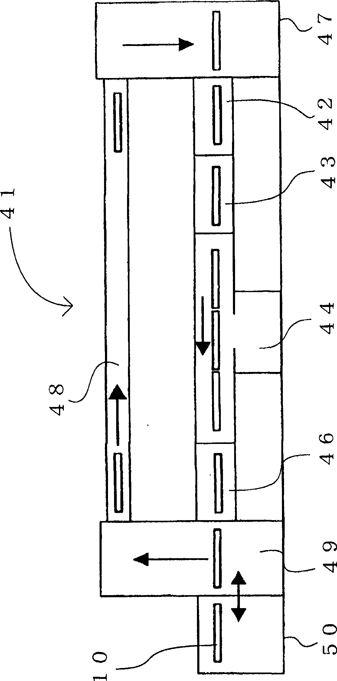
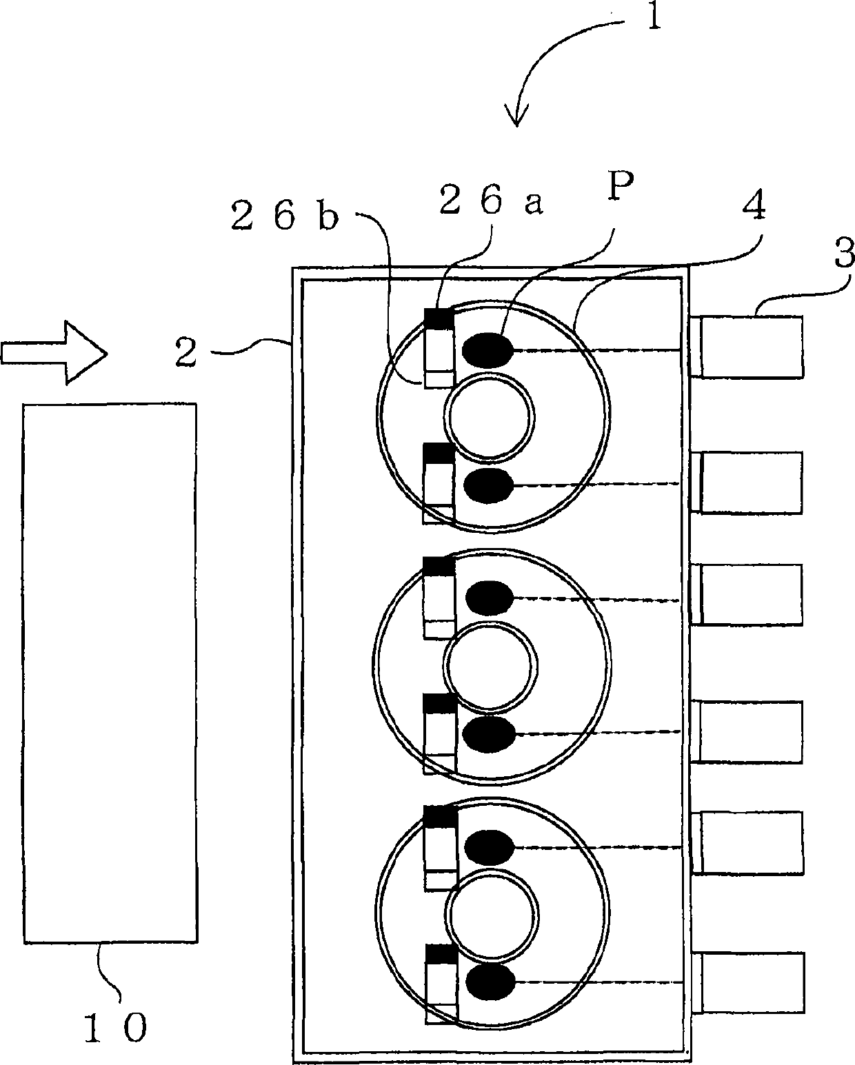
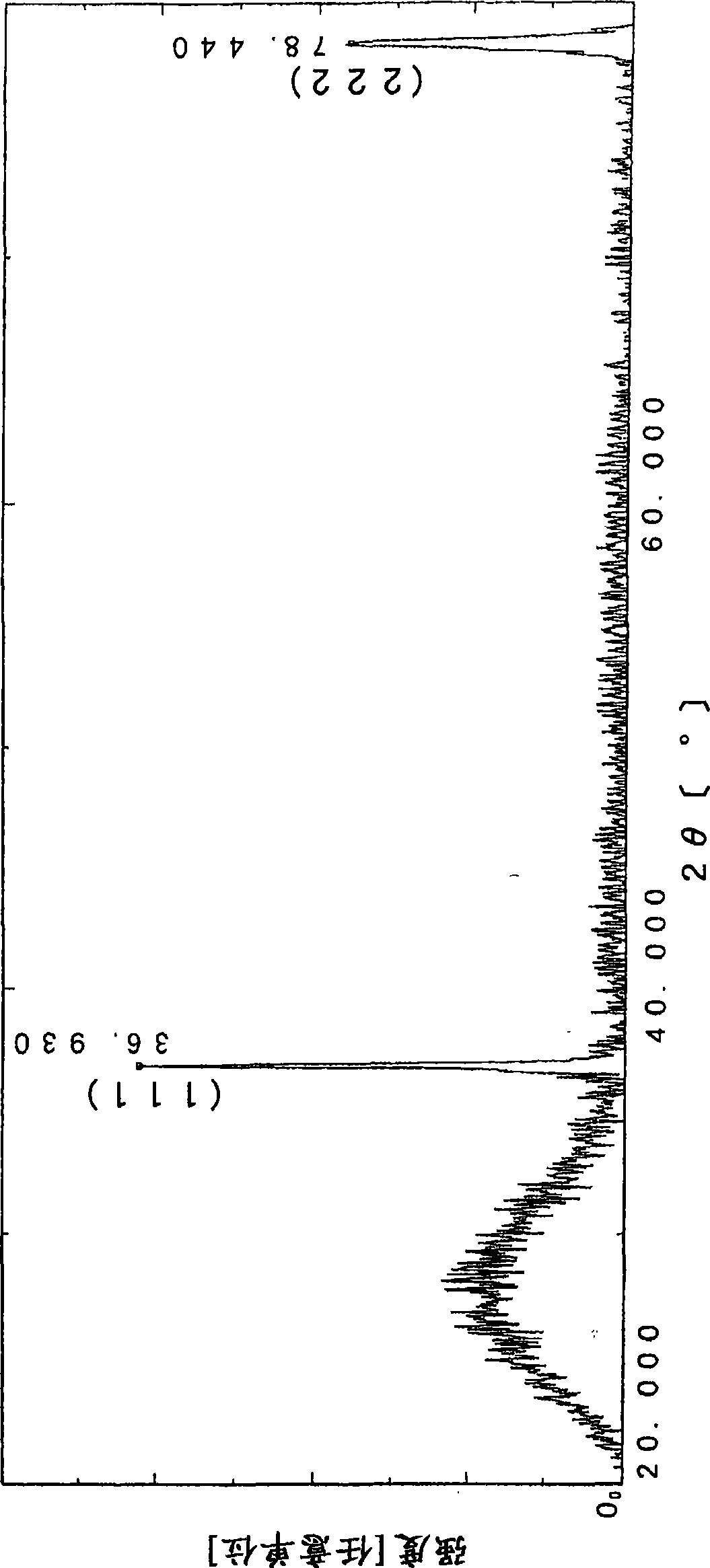
[0130] figure 1 A PDP manufacturing apparatus 41 according to an embodiment of the present invention is shown. Compared with conventional PDP manufacturing equipment ( Figure 10 ) compared to two heating and cooling chambers can be cut. figure 2 It is a figure of the electron beam evaporation source of this embodiment. image 3 It is a figure of the X-ray diffraction pattern of the MgO film formed using the PDP manufacturing apparatus of this embodiment. Figure 4 It is a graph of the film formation rate of the PDP manufacturing apparatus which concerns on embodiment of this invention.

[0131] like figure 1 As shown, the PDP manufacturing apparatus 41 of the embodiment of the present invention is composed of a loading chamber 42, a transfer chamber 43, a vapor deposition chamber 44, an extraction chamber 46, a front elevator 47, a rear elevator 49, and a substrate position 50. Such a heat...

Embodiment 2

[0144] Example 2 is an example in which the present invention is applied to an existing device.


PUM

PropertyMeasurementUnit
thicknessaaaaaaaaaa
angle of incidenceaaaaaaaaaa
refractive indexaaaaaaaaaa

Abstract

Provided is a plasma display panel manufacturing method which simplifies a manufacturing step by lowering a film formation temperature so as to easily obtain an oriented MgO film as a protection layer. Moreover, the manufactured device has a simple structure so as to reduce the tact time. The method is used for manufacturing a plasma display including a front substrate having a scan electrode, a sustain electrode, a dielectric layer, and a protection layer; and a back substrate having an address electrode, a barrier rib, and a fluorescent body. The temperature of a front glass substrate before deposition by an electron beam deposition device is kept at a normal temperature (120 degrees C or below) and the MgO film formation speed of the electron beam deposition device is set not smaller than 8000AA m / min. By the film formation at the normal temperature, it was possible to obtain an MgO film equivalent to the film formation at a high temperature.

Description

technical field [0001] The present invention relates to a manufacturing method and manufacturing apparatus of a plasma display panel (hereinafter referred to as PDP), and particularly relates to formation of a protective layer of a dielectric layer. Background technique [0002] The AC surface discharge PDP, which is the mainstream of current PDPs, includes a front substrate made of scan electrodes, sustain electrodes, a dielectric layer, and a protective layer, and a back substrate made of address electrodes, barrier ribs, and phosphors (refer to Figure 20 ). [0003] like Figure 20 In the shown AC surface discharge type PDP 81, two glass substrates are welded and sealed via a narrow space filled with discharge gas. On rear glass substrate 90 , address electrodes 89 are arranged along the column direction, and dielectric layer 87 is formed thereon. The dielectric layer 87 functions as a protection of the address electrode 89 and a white inversion layer to improve brightn...

Claims


Application Information

Patent Timeline
Patent Type & Authority Applications(China)
IPC IPC(8): C23C14/24C23C14/08H01J9/02H01J11/02H01J17/49
CPCH01J11/40H01J9/02C23C14/081H01J11/12C23C14/568C23C14/08C23C14/24
Inventor 饭岛荣一箱守宗人
Owner ULVAC INC
Why Eureka
Try Eureka