Plasma filming apparatus, and plasma filming method

A plasma and film-forming device technology, applied in semiconductor/solid-state device manufacturing, gaseous chemical plating, coating, etc., can solve the problems of inability to obtain energy, low film-forming rate, and deterioration of uniformity within the film thickness, etc. Effects of preventing decrease in electron density, maintaining in-plane uniformity, and high film formation rate

Inactive Publication Date: 2009-09-02
TOKYO ELECTRON LTD
View PDF5 Cites 3 Cited by
  • Summary
  • Abstract
  • Description
  • Claims
  • Application Information

AI Technical Summary

Problems solved by technology

[0017] However, in this case, since the SiO 2 The binding energy is large, so there is not only a very low film formation rate, but also a problem that the in-plane uniformity of the film thickness deteriorates
The reason is that since the above-mentioned shower head 34 is formed in a grid shape, the grid portion formed in the entire horizontal plane of the processing space S has a plasma shielding function, so the plasma is blocked by the grid portion, and thus cannot obtain enough to form SiO 2 energy of
In this case, although various attempts have been made to change the shape of the gas introduction unit 10, satisfactory results have not yet been obtained.

Method used


Image

  • Plasma filming apparatus, and plasma filming method
  • Plasma filming apparatus, and plasma filming method
  • Plasma filming apparatus, and plasma filming method

Examples


no. 1 Embodiment

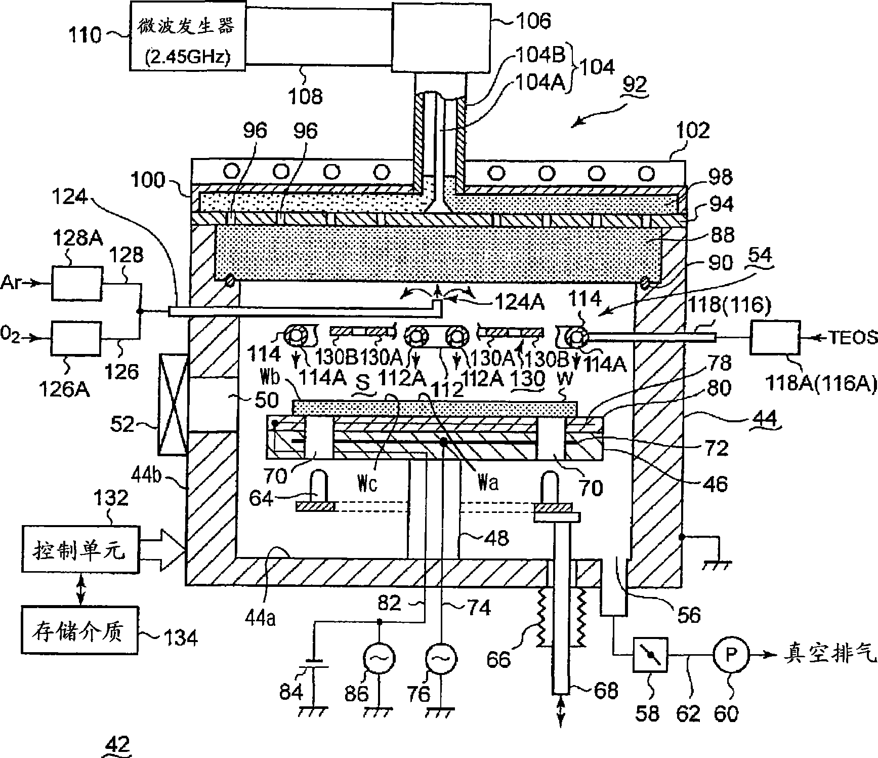
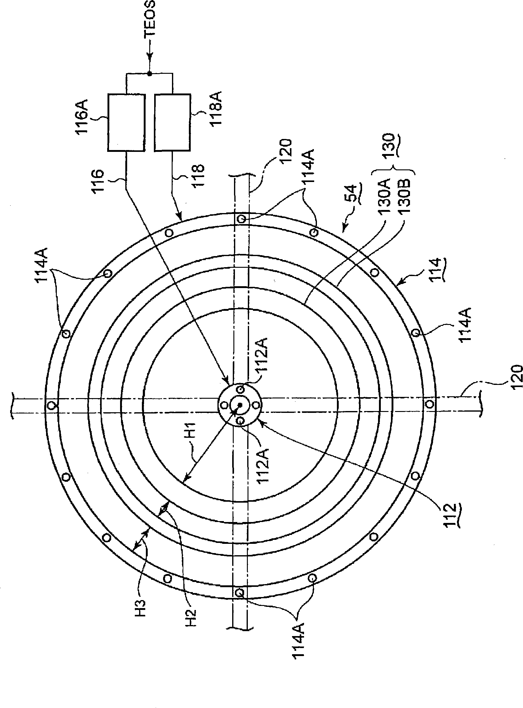
[0055] figure 1 is a configuration diagram showing the first embodiment of the plasma film forming apparatus of the present invention, figure 2 It is a plan view showing the state when the gas introduction unit is viewed from below. Here, TEOS is used as the source gas, and O for oxidation is used as the auxiliary gas. 2 Ar gas for gas and plasma stabilization to form SiO by plasma CVD 2 The case of a thin film composed of a film will be described as an example. In addition, a rare gas such as Ar may be added to the above-mentioned TEOS as needed.

[0056] As shown in the figure, the plasma film forming apparatus 42 has a processing container 44. The side wall and bottom of the processing container 44 are made of conductors such as aluminum, and are integrally formed in a cylindrical shape. The inside of the processing container 44 is sealed, such as circular. A processing space S in which plasma is formed. The processing container 44 itself is grounded.

[0057] A mou...

no. 2 Embodiment

[0114] On the lower surface, a second embodiment of the plasma processing apparatus of the present invention will be described. before using figure 1 The shown first embodiment of the apparatus can improve the in-plane uniformity of the film thickness to a certain extent while maintaining a high film formation rate, but it is desired to further improve the in-plane uniformity of the film thickness. In the previous first embodiment, the assist gas injection hole 124A of the assist gas nozzle portion 124 was provided in the center, thereby supplying O 2 gas, etc., but in order to improve the in-plane uniformity of the film thickness, it is necessary to make the O 2 Shower head structure in which gas and the like are uniformly supplied to the entire processing space S without shielding microwaves. Therefore, in the second embodiment, the top plate 88 forming the top of the processing container is provided with the function of the shower head.

[0115] Figure 7 A schematic c...


PUM

PropertyMeasurementUnit
thicknessaaaaaaaaaa
diameteraaaaaaaaaa

Abstract

Provided is a plasma filming apparatus, which can keep high not only a filming rate but also an in-plane homogeneity of a film thickness. The plasma filming apparatus comprises a treating container (44) made evacuative, a placing bed (46) for placing a treatment object (W) thereon, a ceiling plate (88) mounted in the ceiling and made of a dielectric material for transmitting microwaves, gas introducing means (54) for introducing a treating gas containing a filming raw gas and a support gas, and microwave introducing means (92) having a plain antenna member disposed on the ceiling side for introducing the microwaves. The introducing means includes central gas injection holes (112A) for the raw gas positioned above the central portion of the treatment object, and a plurality of peripheral gas injection holes (114A) for the raw gas arrayed above the peripheral portion of the treatment object and along the peripheral direction of the same. Above the treatment object and between the central gas injection holes (112A) and the peripheral gas injection holes (114A), there are disposed plasma shielding portions (130) for shielding the plasma along the peripheral direction.

Description

technical field [0001] The present invention relates to a plasma film forming apparatus and a plasma film forming method for forming a thin film by applying plasma generated by microwaves to a semiconductor wafer or the like. Background technique [0002] In recent years, with the increase in density and miniaturization of semiconductor products, plasma processing equipment has been widely used in order to perform various processes such as film formation, etching, and ashing in the manufacturing process of semiconductor products. In particular, since microwaves can stably generate plasma even in a high-vacuum state with a relatively low pressure of about 0.1 mTorr (13.3 mPa) to several Torr (hundreds of Pa), microwaves are used to generate high-density plasma. Plasma microwave plasma treatment device. [0003] Such plasma processing apparatuses are disclosed in Patent Documents 1 to 5 and the like. Here, refer to Figure 11 to Figure 13 , a general description will be give...

Claims


Application Information

Patent Timeline
Patent Type & Authority Applications(China)
IPC IPC(8): H01L21/31C23C16/455C23C16/511
CPCC23C16/511H01J37/32623H01J37/3244C23C16/4558C23C16/45565H01J37/32449C23C16/402H01J37/32192H01L21/31608H01J37/32238H01L21/02197
Inventor 上田博一堀込正弘
Owner TOKYO ELECTRON LTD
Why Eureka
Try Eureka