Organic electroluminescence device

a technology of electroluminescence device and organic material, which is applied in the direction of discharge tube luminescnet screen, other domestic articles, natural mineral layered products, etc., can solve the problems of difficult control of the generation of complexation byproducts, and the inability to achieve devices satisfying both high efficiency and durability, and achieves excellent durability and high luminance devices. , the effect of improving the yield in the complexation step

Active Publication Date: 2012-05-29
UDC IRELAND
View PDF61 Cites 2 Cited by
  • Summary
  • Abstract
  • Description
  • Claims
  • Application Information

AI Technical Summary

Benefits of technology

[0008]An object of the invention is to provide a preparation process of a pyridylpyridine platinum complex having a specific structure permitting improvement of a yield in a complexation step; a platinum complex prepared by the preparation process; a pyridylpyridine platinum complex having a specific structure; and an organic electroluminescence device having excellent durability when used as a high luminance device.
[0009]The present inventors have investigated with a view to overcoming the above-described problem and considered that a poor yield of the complexation step of a pyridylpyridine ligand and a platinum (II) salt owes to the coordination of the nitrogen atom of the pyridine ring to platinum. As a result, it has been found that a pyridylpyridine complex can be synthesized in a high yield by introducing an electron withdrawing substituent to the α-position relative to the nitrogen atom of the pyridine ring to control the coordination of the nitrogen atom to platinum (effective for reducing coordination of the nitrogen atom to platinum by the steric repulsion and reducing electron density on the nitrogen atom). It has also been found that the resulting pyridylpyridine complex shows improved durability in use for an organic EL device at high luminance compared with known blue-light emitting materials, leading to the completion of the invention. The present invention is therefore achieved by the following means.

Problems solved by technology

It is however difficult to control generation of complexation byproducts so that establishment of a practical preparation process of them is required.
There is also a report on a blue light emitting material having a pyridylpyrazole skeleton and an organic EL device using it (JP-A-2007-19462), but this development has not succeeded in obtaining a device satisfying both high efficiency and durability particularly when it is used as a high luminance device.

Method used


Image

  • Organic electroluminescence device
  • Organic electroluminescence device
  • Organic electroluminescence device

Examples


example 1

[0230]

Synthesis of Compound J2

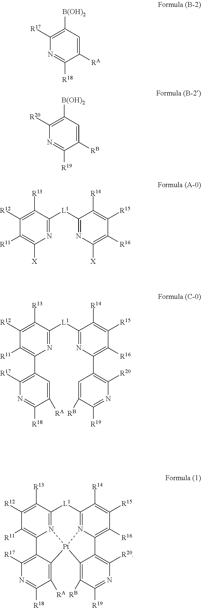
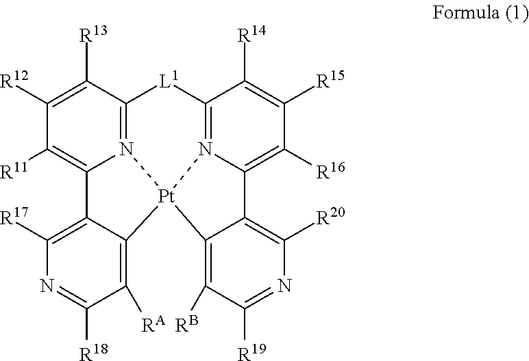
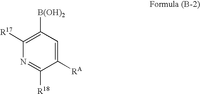
[0231]A mixture composed of Compound A1 (3.56 g, 10.0 mmol), 2-fluoropyridyl-3-boric acid (4.23 g, 30.0 mmol), palladium acetate (0.11 g, 0.5 mmol), triphenylphosphine (0.52 g, 2.0 mmol), sodium carbonate (10.6 g, 0.1 mol), 1.2-dimethoxyethane (100 mL) and water (100 mL) is stirred for 5 hours at 80° C. in a nitrogen atmosphere. After cooling to room temperature, the reaction mixture is filtered, followed by extraction with chloroform. The organic layers are combined, dried, and concentrated. The residue thus obtained is purified by column chromatography. Recrystallization from ethanol is then performed to yield 1.90 g of Compound J2 in the form of white crystals. The yield is 490%.

[0232]1H-NMR (300 MHz, CDCl3) δ: 1.93(s, 6H), 7.21(d, J=9.0Hz, 2H), 7.30(m, 2H), 7.69(t, J=9Hz, 2H), 7.78(d, J=6.0Hz, 2H), 8.23(m, 2H), 8.64(m, 2H).

[0233]

Synthesis of Exemplified Compound 1

[0234]In benzonitrile (50 mL), platinum chloride (2.2 g, 5.0 mmol) and Compound J2 (2.2...

example 2

Synthesis of Compound S2

[0236]

[0237]A mixture composed of Compound A1 (0.83 g, 2.3 mmol), 6-fluoropyridyl-3-boric acid (1.0 g, 7.0 mmol), palladium acetate (26 mg, 0.12 mmol), triphenylphosphine (121 mg, 0.46 mmol), sodium carbonate (2.4 g, 23 mmol), 1,2-dimethoxyethane (25.0 mL) and water (25.0 mL) is stirred for 1.5 hours at 85° C. in a nitrogen atmosphere. After cooling to room temperature, the reaction mixture is filtered with cerite, followed by extraction with ethyl acetate. The organic layers are gathered up, dried, and then concentrated. The residue thus obtained is purified by column chromatography, thereby yielding 0.7 g of Compound S2 in the form of a white solid. The yield is 85%.

Synthesis of Exemplified Compound 2

[0238]

[0239]In a nitrogen atmosphere, platinum chloride (137 mg, 0.52 mmol) and Compound S2 (200 mg, 0.52 mmol) are stirred into benzonitrile (5 mL) for 6.5 hours under heating and refluxing conditions. The reaction mixture is cooled to room temperature, and a ...

example 3

Synthesis of Exemplified Compound 3

[0240]

Synthesis of Compound A2

[0241]In a nitrogen atmosphere, a three-necked flask is charged with Compound A1 (2.0 g, 5.62 mmol), 2,6-difluoropyridyl-3-boric acid (2.14 g, 11.24 mmol), palladium acetate (63 mg, 0.281 mmol), triphenylphosphine (294 mg, 1.12 mmol), sodium carbonate (5.96 g, 56.2 mmol), 1,2-dimethoxyethane (40 ml) and water (40 ml). The resulting mixture is heated under reflux for 6 hours and 30 minutes while stirring. After cooling to room temperature, the reaction mixture is extracted with ethyl acetate. The organic layer thus obtained is dried over sodium sulfate and filtered, followed by concentration. The residue obtained is purified by silica gel column chromatography (chloroform) to yield 1.81 g (yield: 76%) of Compound A2 in the form of white crystals.

[0242]1H-NMR (CD2Cl2, 300 MHz,) δ: 1.95 (s, 6H), 7.00 (ddd, J=0.9, 3.0, 8.1 Hz, 2H), 7.30 (dd, J=2.4, 6.6 Hz, 2H), 7.74-7.80 (m, 4H), 8.72 (dt, J=8.1, 9.6 Hz, 2H)

Synthesis of Ex...


PUM

PropertyMeasurementUnit
temperatureaaaaaaaaaa

Abstract

A process for preparing a platinum complex represented by the following formula (1) includes reacting a compound represented by the following formula (B-2) and a compound represented by the following formula (B-2′) with a compound represented by the following formula (A-0) to obtain a compound represented by the following formula (C-0); and reacting the compound represented by the formula (C-0) with a platinum salt:

Description

BACKGROUND OF THE INVENTION[0001]1. Field of the Invention[0002]The present invention relates to a platinum complex compound useful as a light emitting material and an organic electroluminescence device (which may hereinafter be called “organic EL device”) using the platinum complex compound.[0003]2. Description of the Related Art[0004]Research and development on organic electroluminescence devices are actively performed in recent years because they provide high-luminance emission at a low driving voltage. In general, organic EL devices have organic layers including a light emitting layer and a pair of electrodes sandwiching the organic layers therebetween. Electrons injected from a cathode and holes injected from an anode recombine in the light emitting layer and energy of excitons thus formed is made use of for light emission.[0005]Use of a phosphorescent material has accelerated improvement in efficiency of devices. As the phosphorescent material, iridium complexes and platinum c...

Claims


Application Information

Patent Timeline
Patent Type & Authority Patents(United States)
IPC IPC(8): H01L51/54C09K11/06
CPCC07F15/0086C09K11/06H01L51/0087H01L51/5012H05B33/14C09K2211/1029C09K2211/185Y10S428/917H10K85/346H10K50/11H10K50/00
Inventor MURAKAMI, TAKESHIKINOSHITA, IKUOYAGI, KAZUNARITAKADA, SAKITAKEDA, AKIRASOTOYAMA, WATARUTAKIZAWA, HIROO
Owner UDC IRELAND
Why Eureka
Try Eureka