Freeze-prevention direct air cooling condenser

An air-cooled condenser, direct technology, used in steam/steam condensers, lighting and heating equipment, etc., can solve problems such as energy loss, reduced flow velocity in the tube, freeze cracking of heat transfer tubes, etc., to reduce the time and cost spent , The effect of improving the uniformity of heat exchange and reducing the initial investment cost

Active Publication Date: 2009-09-09
SHUANGLIANG ECO ENERGY SYST CO LTD
View PDF0 Cites 16 Cited by
  • Summary
  • Abstract
  • Description
  • Claims
  • Application Information

AI Technical Summary

Problems solved by technology

When the unit is running, due to the uneven distribution of the steam flow of each tube of the heat transfer tube bundle and the uneven distribution of the air volume of each fan unit (the air volume in the middle of the fan unit is large, and the air volume at the partition walls on both sides is small), the middle of each fan unit The heat transfer driving force of the heat transfer tube increases, which increases the steam flow rate, resulting in an increase in the flow velocity in the tube, and the wind speed outside the tube is greater than that on the side of the wind wall, so that the heat transfer is enhanced; while the steam flow rate of the side row tubes decreases, the flow rate in the tube increases. Reduced, due to the small air volume outside the matching pipe, and the swirling vortex is formed at the corner of the tube bundle at the fan partition wall, resulting in the energy loss of the air supply. With the decrease of the wind speed, the heat transfer effect is reduced, and the amount of steam condensed in the pipe is reduced, resulting in the steam inside The accumulation of entrained non-condensable gas further deteriorates the heat transfer, making the pressure drop of several side tubes larger than that of the middle heat transfer tube
as attached figure 2 As shown, a low-pressure area is formed in the lower half of several side pipes, where non-condensable gas accumulates, and the pressure in the condensed water header is basically the same, resulting in some uncondensed steam in the middle pipe Backflow into several pipes on the side exhaust pipe, so that the non-condensable gas is trapped between the two steams and cannot be discharged
However, in the northern region, when the unit is running in winter, due to the low ambient temperature, the condensed water condensed on the upper parts of the side pipes will gradually cool down to overheating when it flows through these cold non-condensable gas mass areas lacking steam. If it is cold, it will freeze over time, eventually causing the flow channel in the tube to be blocked, and in severe cases, it will cause the heat transfer tube to freeze and crack, with serious consequences

Method used


Image

  • Freeze-prevention direct air cooling condenser
  • Freeze-prevention direct air cooling condenser
  • Freeze-prevention direct air cooling condenser

Examples


Embodiment Construction

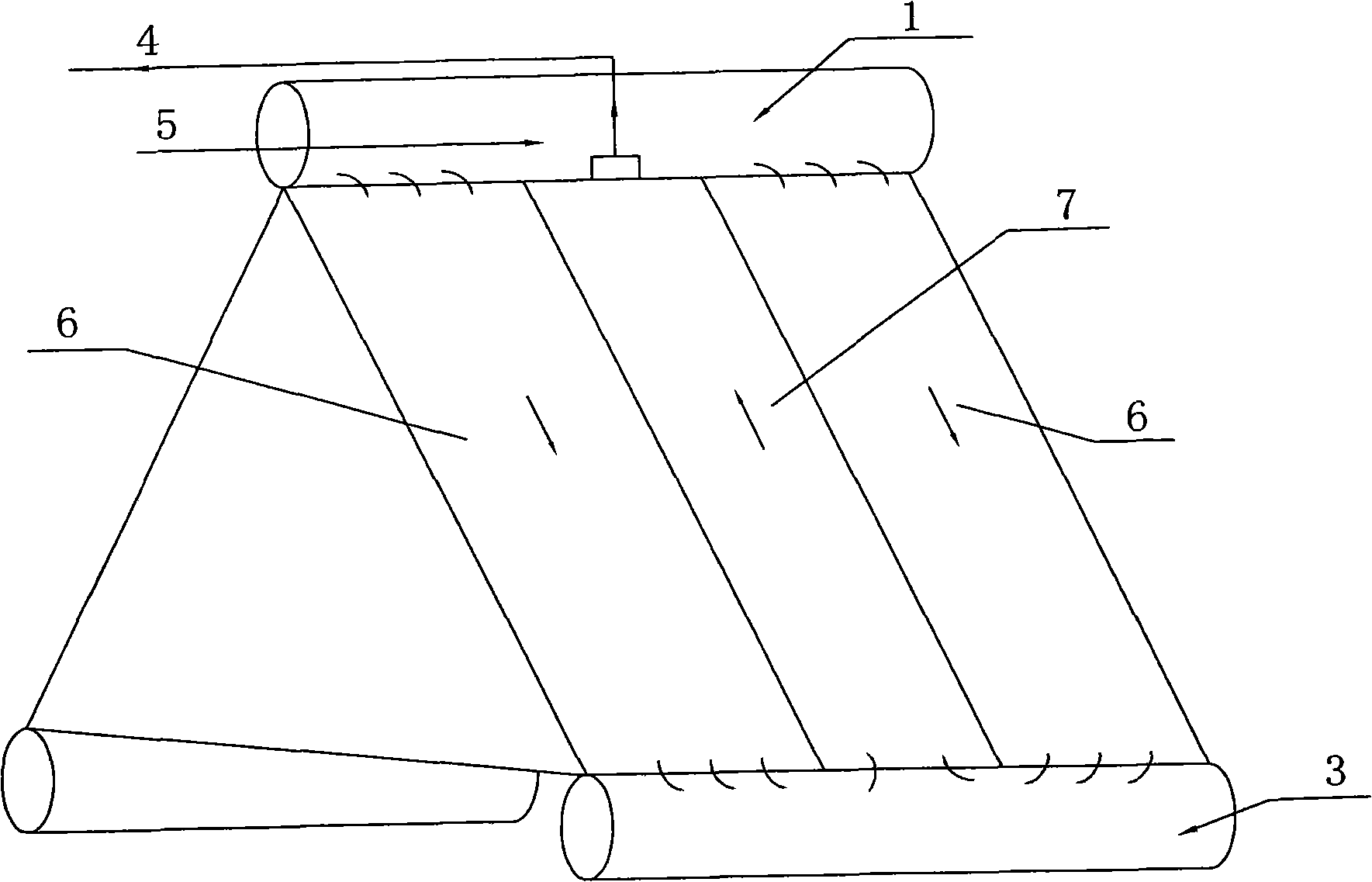
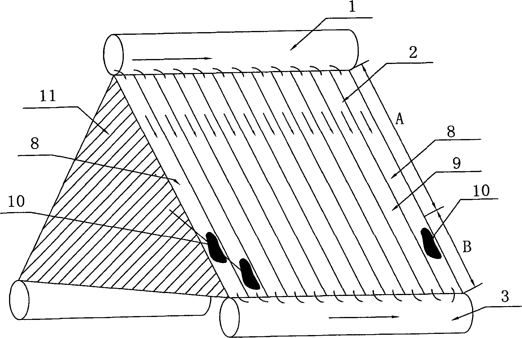
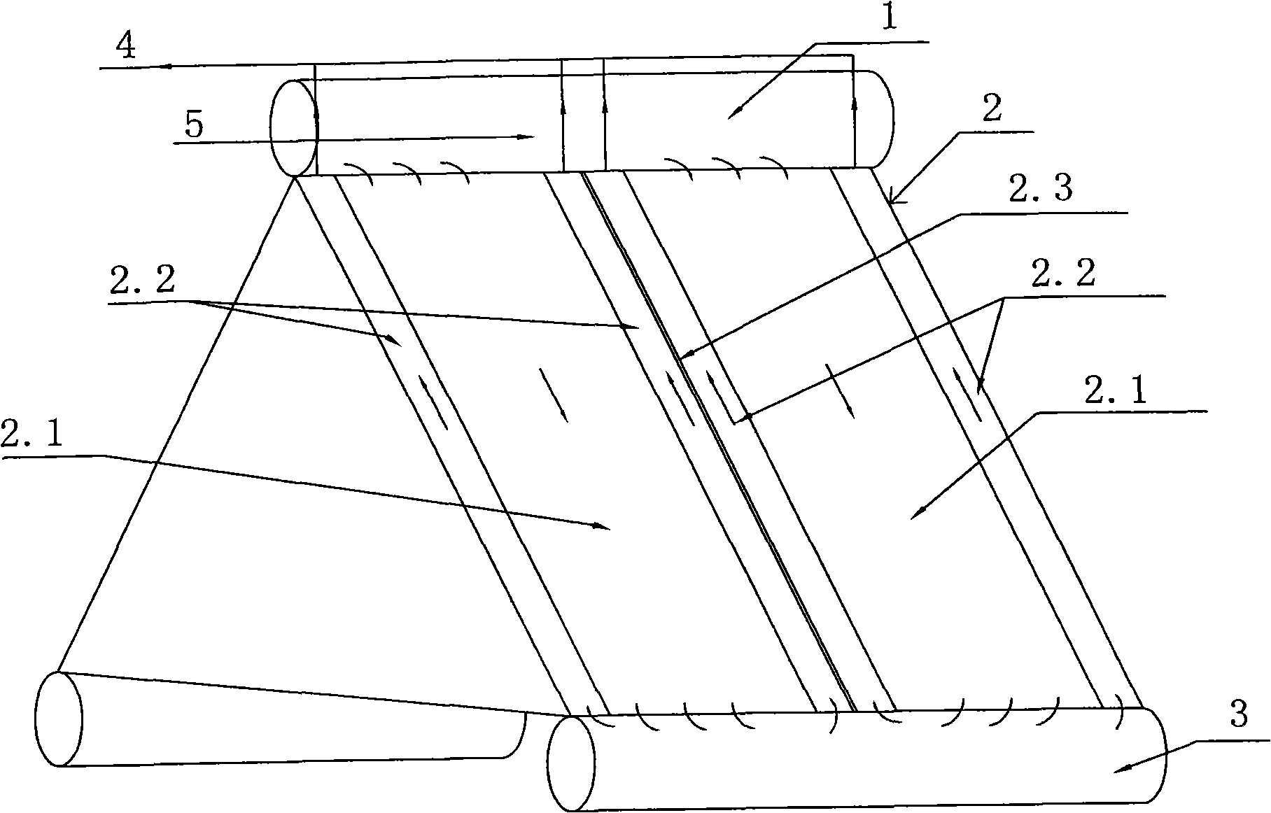
[0015] The present invention prevents the heat exchange tube bundle system of the direct air-cooled condenser such as image 3 , mainly consists of steam distribution pipe 1 (steam inlet), fan unit 2, condensate header 3, vacuum system 4 and condensate pipeline (omitted). There are several fan units 2, and the forward heat transfer tube bundle 2.1 is arranged in the middle position of each fan unit 2 where the wind speed is relatively high, and the counter heat transfer tube bundle 2.2 is arranged at the partition walls on both sides of each fan unit 2 where the wind speed is relatively small. The steam is distributed by the steam distribution pipe into the forward heat transfer tube bundle 2.1 of each fan unit. After heat exchange, most of the steam condenses into water and is discharged through the condensate header 3 through the condensate pipeline. The remaining steam enters the counter heat transfer tube bundle 2.2. After the water vapor is condensed, it is discharged thr...


PUM


Abstract

The invention relates to a freeze-prevention direct air cooling condenser which is suitable for a heat power station lacking of water sources and a turbine direct air cooling condenser system. The freeze-prevention direct air cooling condenser comprises a steam distributing pipe (1), draught fan units (2), a condensing water channel (3), a vacuum-pumping system (4) and a condensing water pipeline, wherein a fair current heat-transfer tube bundle (2.1) is arranged in the middle of each of the plurality of draught fan units (2), reverse current heat-transfer tube bundles (2.2) are arranged at partition walls positioned at both sides of each draught fan unit (2), the fair current heat-transfer tube bundles (2.1) are respectively communicated with the steam distributing pipe (1) and the condensing water channel (3), and the reverse current heat-transfer tube bundles (2.2) are respectively communicated with the condensing water channel (3) and the vacuum-pumping system (4). The invention can eliminate the root of the freeze of a system, i.e. steam refluence is generated between fin heat exchange tubes due to unbalanced pressure to enable uncondensed gas to be accumulated in the middle of heat-transfer pipes so as to enable upper-part condensing water to be frozen due to supercooling when passing through the uncondensed gas when downwards flowing along the heat-transfer pipes.

Description

(1) Technical field [0001] The invention relates to a direct air-cooled condenser, which is suitable for direct air-cooled condenser systems of thermal power stations and turbines lacking in water sources. (2) Background technology [0002] The direct air-cooled condenser system consists of heat exchange tube bundles, tube bundle support A-frames, fan groups, steel platforms, windshield walls, steam pipes, condensate water pipes, vacuum pipes, water ring vacuum pumps (steam ejectors) and Composition of electrical control system. The direct air-cooled condenser uses a fan to blow the heat exchange tube bundle, and condenses the water vapor from the generator / turbine into water in the heat exchange tube bundle to keep the discharge pressure of the generator set / turbine set stable at the design value. . The heat transfer tube bundles are arranged according to a certain "K / D" ratio. [0003] The system layout scheme of the forward and reverse flow unit of the air-cooled conde...

Claims


Application Information

Patent Timeline
IPC IPC(8): F28B1/06
Inventor 王永新薛海君江瀚
Owner SHUANGLIANG ECO ENERGY SYST CO LTD
Why Eureka
Try Eureka