
Gallium arsenide monolithic integrated numerical-control real time delay circuit

A monolithic integration, integrated circuit technology, applied in delay lines, circuits, electrical components, etc., can solve the problem that fiber optic delay devices or microwave hybrid circuits cannot meet the requirements of batch engineering, increase circuit complexity, delay accuracy, problems such as the influence of electrical performance, to achieve the effect of good electrical performance consistency, simplifying complexity, and reducing volume

Active Publication Date: 2009-09-09
河北新华北集成电路有限公司
View PDF0 Cites 8 Cited by
  • Summary
  • Abstract
  • Description
  • Claims
  • Application Information

AI Technical Summary

Problems solved by technology

[0003] With the requirements of miniaturization and batching of electronic transceiver systems, the optical fiber delayer or microwave hybrid circuit used in the system cannot meet the requirements of batch engineering
At the same time, the current delay line circuit makes the delayed signal fluctuate to a certain extent. It is necessary to increase the amplitude adjustment circuit to adjust the signal amplitude, which increases the complexity of the circuit. At the same time, its delay accuracy and electrical performance are also affected to a certain extent. influences

Method used


Image

  • Gallium arsenide monolithic integrated numerical-control real time delay circuit
  • Gallium arsenide monolithic integrated numerical-control real time delay circuit
  • Gallium arsenide monolithic integrated numerical-control real time delay circuit

Examples


Embodiment Construction

[0017] The present invention is described in further detail below in conjunction with accompanying drawing:

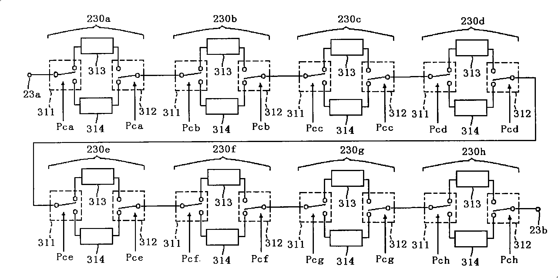
[0018] The present invention adopts the integrated circuit manufacturing process, and the basic delay bit circuit elements are manufactured on the substrate (substrate) by thin film technology, and a plurality of basic delay bit circuits with different delay times are integrated in the same chip, and all the basic delay bit circuits are integrated in the same chip. The bit circuits are connected in series, and each basic delay bit circuit includes a single-pole double-throw switch module, a delay module, and an amplitude adjustment module, and its structural block diagram is as follows figure 2 As shown, the common terminal of the SPDT switch module is connected to the input signal, the other two ports are respectively connected to the input terminals of the delay module and the amplitude adjustment module, and the output terminals of the delay module and the amplitude...


PUM


Abstract

The invention discloses a gallium arsenide monolithic integrated numerical-control real time delay circuit which consists of different basic delay potentials and is characterized in that more than two different basic delay potentials are integrated on the same chip by adopting the integrated circuit technology and the basic delay potentials are connected in series, wherein, each basic delay potential comprises single-pole double-throw switch modules, a delay module and an amplitude adjustment module; the common terminal of one single-pole double-throw switch module is connected with the input signals, and the other two terminals thereof are connected with the input terminals of the delay module and the amplitude adjustment module respectively; and the common terminal of the other single-pole double-throw switch module is the signal output terminal, and the output terminals of the delay module and the amplitude adjustment module are connected with the other two ends thereof. The invention can improve the delay precision, so that better consistency of electrical properties is ensured and the invention is least controlled and affected by the technology; meanwhile, the invention increases the signal amplitude adjustment circuit, compensates for the amplitude fluctuation of the delay branch, fulfils the functions of a plurality of circuits in the transceiver system and reduces the complexity of the system.

Description

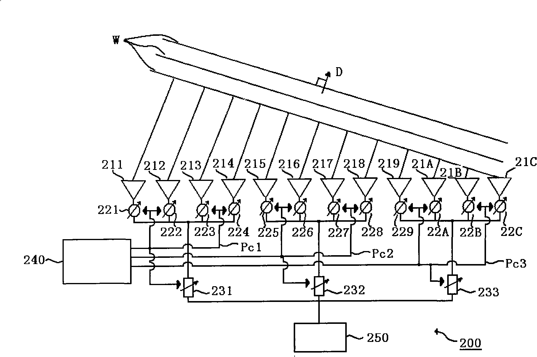
technical field [0001] The present invention relates to a method of selecting and controlling the transmission time of the modern advanced electronic transceiver system to realize the simultaneous arrival of multi-channel microwave signals at the signal processing center unit, so as to accurately realize the radio frequency beam pointing and tracking of the electronic transceiver system, especially a A gallium arsenide monolithically integrated digitally controlled real-time delay line circuit. Background technique [0002] Real-time delay line circuits are widely used as a component in microwave transceiver systems, such as figure 1 As shown, it is a structural block diagram of a simplified electronic transceiver system. The electronic transceiver system 200 includes 12 antenna units 211, 212, 213, 214, 215, 216, 217, 218, 219, 21A, 21B and 21C, and 221, 222, 223, 224, 225, 226, 227, 228, 229, 22A, 22B and 22C are 12 phase shifter units in total, and each antenna unit is c...

Claims


Application Information

Patent Timeline
IPC IPC(8): H03H7/30H01P9/00
Inventor 方园吴洪江高学邦李富强谢媛媛刘志军王向玮魏洪涛赵伟崔玉兴
Owner 河北新华北集成电路有限公司
Learn More