Optical member adhering method, and apparatus using the method

A technology for laminating devices and optical components, applied in the direction of optical elements, optical elements, chemical instruments and methods, etc., can solve problems such as poor quality, achieve the effect of maintaining quality, high quality, and reducing dust adhesion

Active Publication Date: 2009-09-09
NITTO DENKO CORP
View PDF3 Cites 54 Cited by
  • Summary
  • Abstract
  • Description
  • Claims
  • Application Information

AI Technical Summary

Problems solved by technology

Furthermore, for the board|substrate used in the conventional apparatus, in order to convey and handle it to the next step under the state where the phot

Method used


Image

  • Optical member adhering method, and apparatus using the method
  • Optical member adhering method, and apparatus using the method
  • Optical member adhering method, and apparatus using the method

Examples


Embodiment Construction

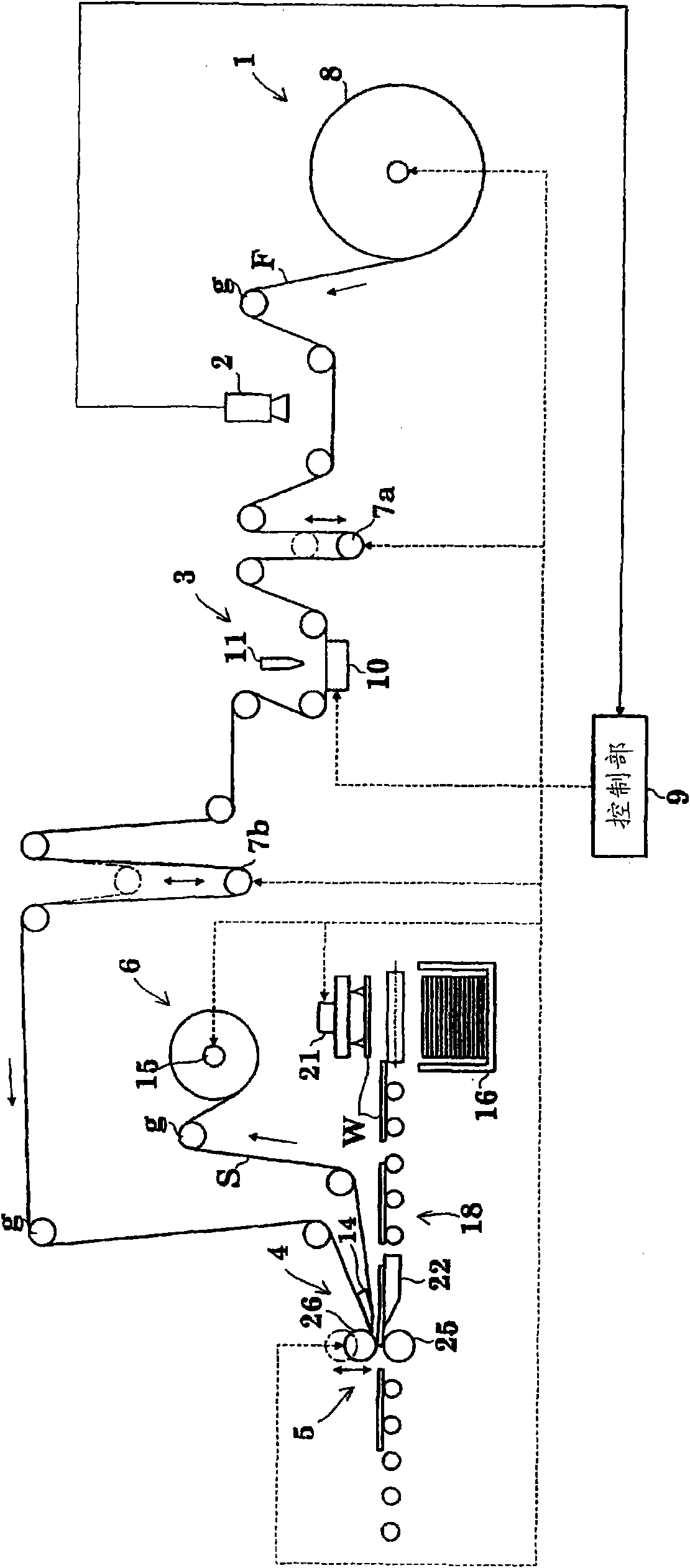
[0098] Embodiments of the present invention will be described below with reference to the drawings. In addition, in the present invention, the optical member is not particularly limited as long as it is a flexible strip-shaped functional film such as a polarizing film, a retardation film, or a brightness improvement film. In this embodiment, the case where a polarizing film is used is taken as an example and described. In addition, the monolithic body of the present invention is not particularly limited as long as it is a functional film such as a polarizing film, a retardation film, and a brightness-enhancing film, a polarizing plate, and a liquid crystal panel. In this embodiment, a liquid crystal panel is used as an example for description. .

[0099] In addition, both the separation film and the protective film of the present invention cover and protect an optical member or a polarizing film in order to prevent surface damage and the like. Here, the separation film can b...


PUM


Abstract

A band-shaped polarization film (F), which has a protection film extended on one face and a separator extended on the other face, is let off and fed from a film feeding unit (1), and is subjected to a visual inspection. The protection film and the polarization film (F) are then half-cut by a laser device (11) while leaving the separator. After this, the films are transferred and guided to a peeling mechanism (4) so that the polarization film (F) is fed, while the separator being peeled by a knife edge, into an adhering mechanism (5). In synchronism with this feeding action of the polarization film (F), a liquid crystal panel (W) fed from a panel transfer device (18) is transferred and guided to the adhering mechanism (5), and the polarization film (F) is adhered to the liquid crystal panel (W).

Description

technical field [0001] The present invention relates to a lamination method of optical members constituted by laminating optical members such as polarizing films, brightness-enhancing films, and phase difference films automatically, at high speed and with high precision, on a single-piece body such as a liquid crystal panel, and the method using the method. device. Background technique [0002] Conventionally, an optical member and a substrate as a single piece are bonded as follows. Continuously transport multiple substrates at a predetermined pitch, and supply a belt-shaped photosensitive product composed of a photosensitive resin layer and a base film, from which the protective film has been peeled off during the process of being pulled out from the raw material roll (original reel). layer film. Next, the substrate and the photosensitive laminated film are sent into the gap between a pair of heating rollers for thermocompression bonding. Thereafter, the substrate bonde...

Claims


Application Information

Patent Timeline
IPC IPC(8): B29C65/78G02B5/30G02F1/13G02F1/1335B23K26/38B23K26/40B29C65/48B32B7/02G09F9/00
CPCB23K26/0846B29D11/0073B32B37/182B32B38/0004B32B38/10B32B41/00B32B2041/04B32B2307/40B32B2310/0843B32B2457/202G01N21/8422G02F1/1303G02F1/133305G02F1/133528B23K26/40B32B2305/55B32B2307/42G02B5/3016B23K2101/16B23K2103/172Y10T156/1057Y10T156/1056Y10T156/12B29C65/78G02B5/30G02F1/13G02F1/1335
Inventor 北田和生龟田祥弘西田干司由良友和天野贵一大桥宏通日野敦司松尾直之
Owner NITTO DENKO CORP
Why Eureka
Try Eureka