Built-in battery pack for mobile communication terminal and method of manufacturing the same

A mobile communication terminal and built-in technology, which is applied in the field of built-in battery packs for mobile communication terminals and its manufacturing, can solve problems such as defective products, complex product structures and manufacturing processes, and increased man-hours, so as to reduce man-hours and costs, reduce Product defect rate, effect of reducing the number of parts

Inactive Publication Date: 2009-09-16
BETESH ENERGY
View PDF0 Cites 5 Cited by
  • Summary
  • Abstract
  • Description
  • Claims
  • Application Information

AI Technical Summary

Problems solved by technology

[0004] In particular, for PCM950, the cathode nickel sheet 941 and the anode nickel sheet 942 that are electrically connected to the cathode terminal 901 of the battery cell 900 and one side connection portion of the PTC 920 respectively are soldered and combined by independent soldering. Due to the characteristics of soldering, it is difficult to perform accurate soldering operations, and the unheated circuit may be defective due to soldering heat.
[0005] That is, in this battery pack product manufacturing method, the anode nickel sheet and the cathode nickel sheet as the anode and cathode terminals are welded on the PCM (protection circuit module) by manual soldering, so the work efficiency is low, not strong enough, and lacks Component assembly space required for surface mount technology (SMT: SurfaceMount Technology)
[0006] In addition, in addition to the welding of the anode and cathode nickel sheets 942 and 941 in PCM950, it is also necessary to spot weld the anode and cathode terminals 902 and 901 of the battery cell. In this way, the weldi

Method used


Image

  • Built-in battery pack for mobile communication terminal and method of manufacturing the same
  • Built-in battery pack for mobile communication terminal and method of manufacturing the same
  • Built-in battery pack for mobile communication terminal and method of manufacturing the same

Examples


Embodiment Construction

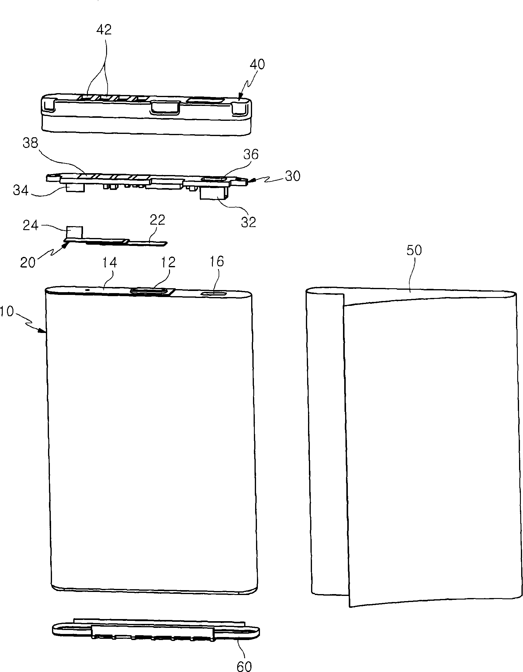
[0037] Hereinafter, preferred embodiments of the present invention will be described in detail with reference to the accompanying drawings. When describing the structure of the power supply (connection) terminal of the present invention, the anode terminal and the cathode terminal are indicated by different reference symbols, but the polarities may be reversed during design. In addition, in the description of the structure of the present invention, for the convenience of explanation, the anode and cathode terminals 16, 12 of the battery cell 10 as connection terminals, the connection parts 22, 24 of the PTC 20, and the anode and cathode nickel sheets 32, 34 of the PCM30 are sometimes They will be described together and the reference signs will be omitted.

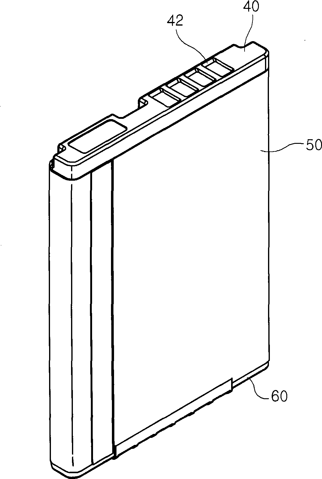
[0038] figure 1 It is a schematic diagram of the combined state of the built-in battery pack according to the manufacturing method of the present invention; figure 2 For the manufacturing method according to the present...


PUM


Abstract

The invention relates to a built-in battery pack for mobile communication terminal and a method of manufacturing the same; for the anode/cathode terminal of the battery pack, the invention does not soldering but uses precise spot welding mode to weld the anode/cathode nickel sheets of PCM and one side connecting portion of PTC, which simplifies the product structure and operating procedures and reduces the badness caused by soldering. The battery pack comprises a battery unit formed with an anode terminal and a cathode terminal at the upper side for charging and discharging; PTC, when mounting, one side connecting portion of bimetal function located at the upper part of the cathode terminal of the battery pack; PCM, the anode and cathode nickel sheets provided at the lower side by surface assemble in raised manner and spot welded one the other side connecting portion of the PTC and the anode terminal of the battery pack formed with corresponding spot welding holes on the upper side; a top cover combined in the upper side of the battery pack and penetrated with corresponding external connecting hole for exposing the external connecting terminal formed on the upper side of the PCM; a bottom cover combined in the lower side of the battery unit; a packing label for packing the battery pack.

Description

technical field [0001] The present invention relates to a built-in battery pack for mobile communication terminals in which battery unit constituent parts are welded together only by spot welding, and more particularly relates to a battery pack that does not use Soldering and only using spot welding can easily and easily weld the anode / cathode nickel sheet combined with PCM (overcharge protection circuit module) and one side connection part of PTC (overcurrent protection element), thus greatly simplifying the product structure and operation A built-in battery pack for mobile communication terminals and a manufacturing method thereof, which structurally reduce the defective rate of products caused by soldering. Background technique [0002] Recently, with the popularization of mobile communication terminals, various battery products have appeared. Compared with external battery packs, built-in battery packs are more popular. With the gradual miniaturization and thinning of m...

Claims


Application Information

Patent Timeline
IPC IPC(8): H01M2/20H01M2/34H01M2/30H01M2/06H01M2/02H04B1/38
CPCY02E60/12Y02E60/10H01M10/4257H01M2200/101H01M2200/106H01M2220/30
Inventor 朱洪杓
Owner BETESH ENERGY
Why Eureka
Try Eureka