RF power amplifier stability network

A network and power technology, applied in amplifiers, amplifiers with semiconductor devices/discharge tubes, components of amplifiers, etc., can solve problems such as low fidelity

Inactive Publication Date: 2009-09-16
MKS INSTR INC
View PDF1 Cites 5 Cited by
  • Summary
  • Abstract
  • Description
  • Claims
  • Application Information

AI Technical Summary

Problems solved by technology

So the fidelity i

Method used


Image

  • RF power amplifier stability network
  • RF power amplifier stability network
  • RF power amplifier stability network

Examples


Embodiment Construction

[0027] The following description of the various embodiments is merely exemplary in nature and is in no way intended to limit the teachings, application or uses of the present invention. Throughout the application, the same reference numerals designate similar elements.

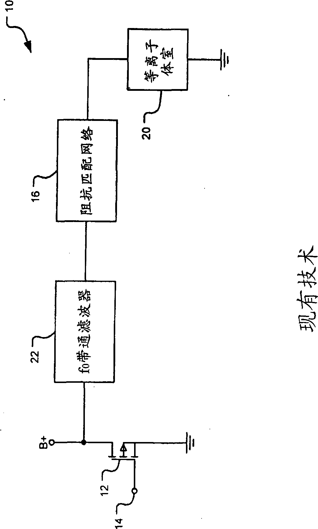
[0028] now refer to Figure 5 , one of several embodiments of a plasma processing system 100 is shown. The direct current (DC) voltage B+ can be generated by half-bridge and / or full-bridge switching power supplies. A low-pass terminated DC feed network (LPT network) 101 wired with the DC feed connects B+ to the drain and collector of the RF transistor 102 . The LPT network 101 is reactive in the frequency band and dissipates at a first cut-off frequency f c1 RF power that occurs below. In various embodiments, the first cutoff frequency f c1 Usually less than the center frequency f 0 . The LPT network 101 will be described in more detail below.

[0029] Transistor 102 is shown as a single metal oxide si...


PUM


Abstract

A radio frequency (RF) generator for applying RF power to a plasma chamber includes a DC power supply (B+). A radio frequency switch generates the RF power at a center frequency f0. A low-pass dissipative terminated network connects between the DC power supply (B+) and the switch and includes operates at a first cutoff frequency. The switch outputs a signal to an output network which improves the fidelity of the system. The output network generates an output signal fed to a high-pass subharmonic load isolation filter that passes RF power above a predetermined frequency. A low-pass harmonic load isolation filter may be inserted between the output network and the high- pass subharmonic load isolation filter, and a high-pass terminated network may connect to the output of the output network. The high-pass terminated network dissipates RF power above a predetermined frequency. An offline short or shunt network may connect between the output of the switch and the input of the output network for shorting the output of the switch at predetermined frequencies.

Description

technical field [0001] The present invention relates to systems and methods for stabilizing radio frequency (RF) power amplifiers in plasma processing systems. Background technique [0002] The statements in this section merely provide background information related to the present disclosure and may not constitute prior art. [0003] Plasma processing systems are used in semiconductor manufacturing. The system employs a plasma chamber that alters the electrical properties of a raw material, such as silicon, to fabricate semiconductor components. Examples of such components include transistors, dielectric and bulk inductors, microprocessors, and random access memories. The plasma chamber is capable of performing sputtering, plasma etching, plasma deposition, and / or reactive ion etching during fabrication. [0004] In operation, the plasma chamber houses a semiconductor workpiece. The gas is then introduced into the plasma chamber at low pressure. An RF power generator ap...

Claims


Application Information

Patent Timeline
IPC IPC(8): H05H1/36
CPCH03F3/265H01J37/32174H01J37/32082H05H1/46H03F1/301H03F3/2171H05H1/36
Inventor 萨尔瓦托雷·波利佐
Owner MKS INSTR INC
Why Eureka
Try Eureka