Steel slag wind-crushing system

A technology for processing systems and steel slag, applied in the direction of recycling technology, etc., can solve problems such as environmental adverse effects, limited resource loss, and increased operating costs, and achieve the effects of improving the level of automation control, solving hot deformation, and improving service life

Inactive Publication Date: 2009-09-23
马钢设计研究院有限责任公司
View PDF0 Cites 10 Cited by
  • Summary
  • Abstract
  • Description
  • Claims
  • Application Information

AI Technical Summary

Problems solved by technology

[0004] 1. Separation of pretreatment and deep processing, steel slag is transported twice, which increases operating costs, or without deep processing, steel slag is not separated from slag and steel, and limited resources are lost;
[0005] 2. Occupy arable land, special slag yard and deep processing line, causing secondary pollution;
[0006] 3. The steel slag stored in the pool can only be grasped by the crane in the gap between the wind and the wind, and the operating time of the crane is limited, which has potential safety hazards and cannot meet the needs of continuous production;
[0007] 4. The granulator is deformed due to high-speed air friction and scorching heat, resulting in disordered air flow and affecting the granulation effect of steel slag;
[0008] 5. The noise, dust and steam in the wind crushing will have adverse effects on the environment

Method used


Image

  • Steel slag wind-crushing system
  • Steel slag wind-crushing system
  • Steel slag wind-crushing system

Examples


Embodiment Construction

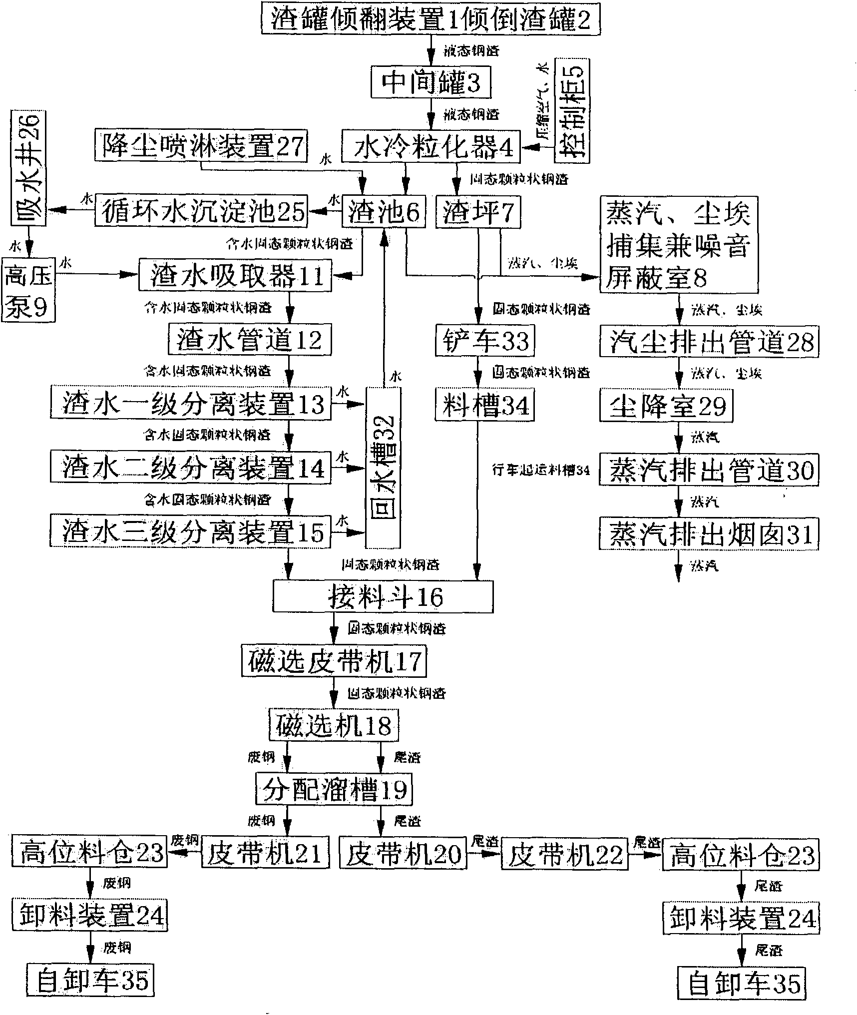
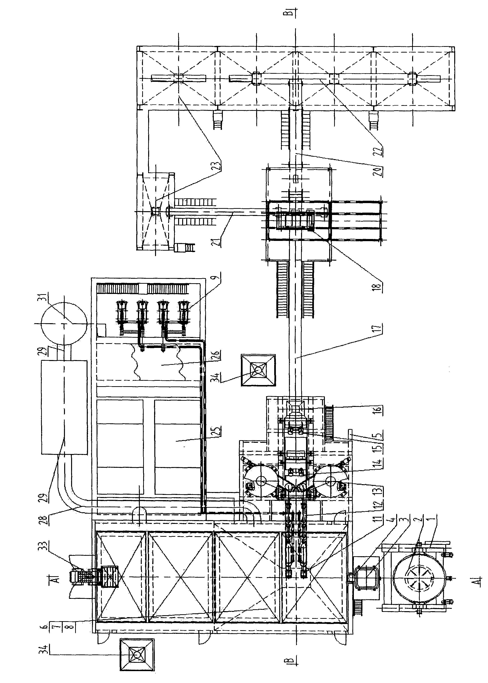
[0031] Such as image 3 The steel slag wind-crushing treatment system shown includes a steel slag pretreatment device, a slag-steel separation device, and a product conveying, loading and unloading device. The pretreatment device includes a tundish 3, a water-cooled granulator 4, a slag pool 6, a slag floor 7, and a control cabinet 5 connected in sequence, and the slag-steel separation device and product conveying, loading and unloading device include a magnetic separation belt conveyor 17 connected in sequence , magnetic separator 18, distribution chute 19, tailings belt conveyor 20, scrap steel belt conveyor 21, belt conveyor 22, high-level feed bin 23 and unloading device 24, it is characterized in that: the slag pond 6 in the steel slag pretreatment device and A slag water suction and separation device is provided between the magnetic separation belt conveyor 17 in the slag-steel separation device located on the right outer side of the slag pool 6; in addition, a water cir...


PUM

PropertyMeasurementUnit
diameteraaaaaaaaaa
diameteraaaaaaaaaa

Abstract

The invention relates to a steel slag wind-crushing system which belongs to the steel slag treatment and is characterized in that a slag water sucking and separating device is arranged between a slag tank in a slag pretreating device and a magnetic separation belt in a slag separating device, wherein the slag water sucking and separating device mainly comprises a slag water sucker, a slag water pipeline, a slag water primary separating device, a slag water secondary separating device and a slag water third-stage separating device, a water return tank is arranged between the slag water primary separating device, the slag water secondary separating device and the slag water third-stage separating device and the slag tank; the outer side of a slag place is provided with a water circulating device, the water circulating device comprises a circulating water sedimentation tank, an absorbing well and a high-pressure pump which are sequentially connected, the high pressure pump is connected with the slag water sucker through a pipe, the periphery of a water-cooling granulator is additionally provided with a water-cooling sleeve and a water inlet pipe, a steam and dust collector of a dust-laying spraying device and a noise shielding chamber are arranged above the slag place of the slag tank, and the shielding chamber is externally provided with a steam and dust discharging pipe, a dust-laying chamber, a steam discharging pipeline and a steam discharging chimney which are sequentially connected. The invention treats the slag on-line so as to effectively utilize the resource, lowers the cost and reduces the consumption, saves the energy and reduces the emission, thereby meeting the environmental-friendly requirement.

Description

technical field [0001] The invention belongs to metallurgical steelmaking steel slag treatment, in particular to a steel slag treatment system. Background technique [0002] Steel slag treatment is an important link in the production chain of the modern metallurgical industry. Its technological process and treatment methods not only determine the work efficiency and treatment cost of steel slag treatment, but also directly lead to the availability of its products, and at the same time bring different impacts on the environment. influences. [0003] The original steel slag treatment technology is generally on-line pretreatment of high-temperature liquid steel slag and off-line deep processing of normal-temperature solid steel slag. There are many methods for on-line pretreatment of high-temperature liquid steel slag, which are generally arranged close to the smelting furnace, among which steel slag air crushing and granulation is one of the more typical methods; normal-tempe...

Claims


Application Information

Patent Timeline
Patent Type & Authority Applications(China)
IPC IPC(8): C21B3/06
CPCY02W30/50
Inventor 沈建中乌力平毛一平陈家庆邱艳生吴文华
Owner 马钢设计研究院有限责任公司
Why Eureka
Try Eureka