
Full automatic atmospheric polarization mode image acquisition system and system control method

An atmospheric polarization mode and image acquisition technology, which is applied in electrical program control, measuring light polarization, program control in sequence/logic controller, etc., can solve problems such as large additional polarization degree of the system, complex system composition, and experimental failure , to achieve the effect of overcoming mechanical vibration, accurate result analysis and shortening the shooting time

Inactive Publication Date: 2009-09-23
HEFEI UNIV OF TECH
View PDF0 Cites 26 Cited by
  • Summary
  • Abstract
  • Description
  • Claims
  • Application Information

AI Technical Summary

Problems solved by technology

[0004] The system has the following deficiencies in the specific implementation, and the detection of atmospheric polarization information cannot be realized simply and conveniently
[0005] 1. The system composition is complex, and the whole system requires a complete set of precision optical transition devices, especially the optical imaging system requires high precision and high cost, which increases the difficulty of implementation and error control
[0006] 2. The system uses a fisheye lens as the imaging lens of the optical system. Although the measurement speed is improved, when the light from a large angle is incident, it will bring a large additional degree of polarization to the system and a large error. The measurement results do not reflect the distribution of the actual mode very well
[0007] 3. The system uses ordinary polarizers. During the shooting process, it needs to rely on stepping motors to realize three rotations of different polarizers. The rotation process takes a long time and the accuracy is not high, which is prone to angle errors.
In addition, the mechanical rotation of the stepping motor inevitably brings mechanical vibration, and any change in the shooting area due to mechanical vibration will directly lead to the failure of the experiment

Method used


Image

  • Full automatic atmospheric polarization mode image acquisition system and system control method
  • Full automatic atmospheric polarization mode image acquisition system and system control method
  • Full automatic atmospheric polarization mode image acquisition system and system control method

Examples


Embodiment Construction

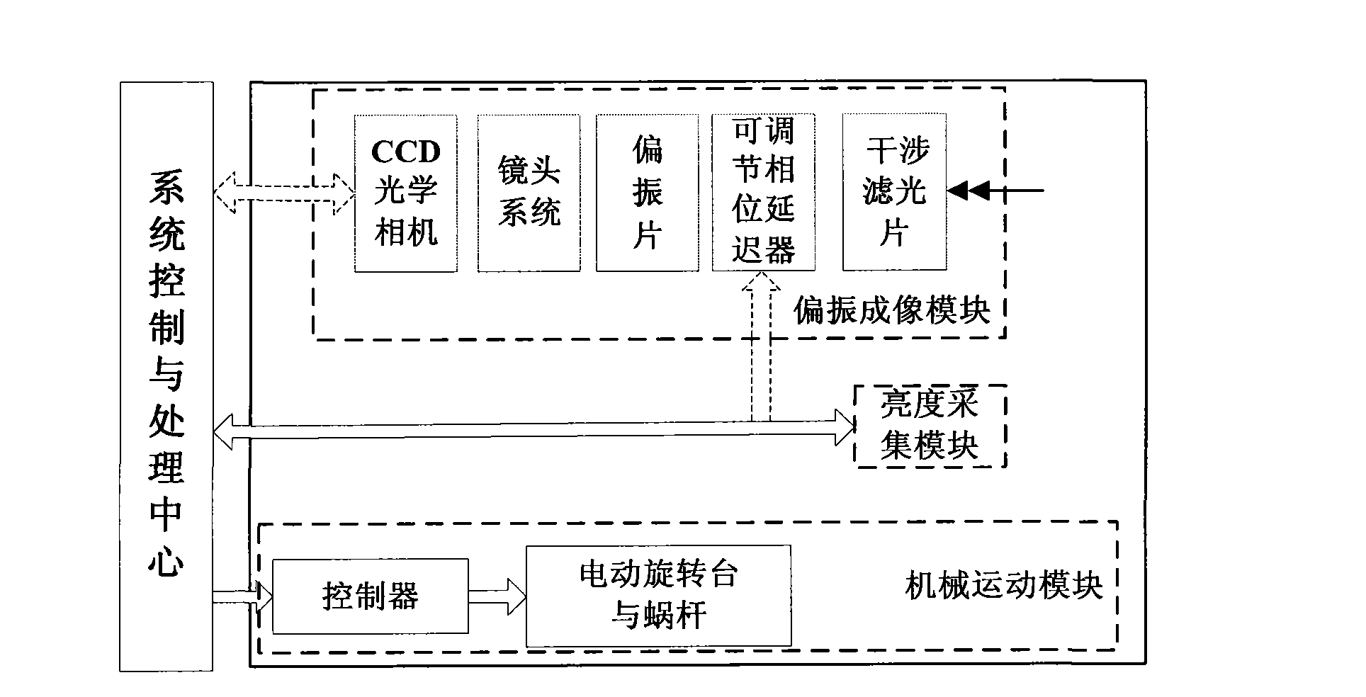
[0040] see figure 1 , the system of this embodiment includes a polarization imaging module, a mechanical movement module, a brightness acquisition module, and a system control and processing center.

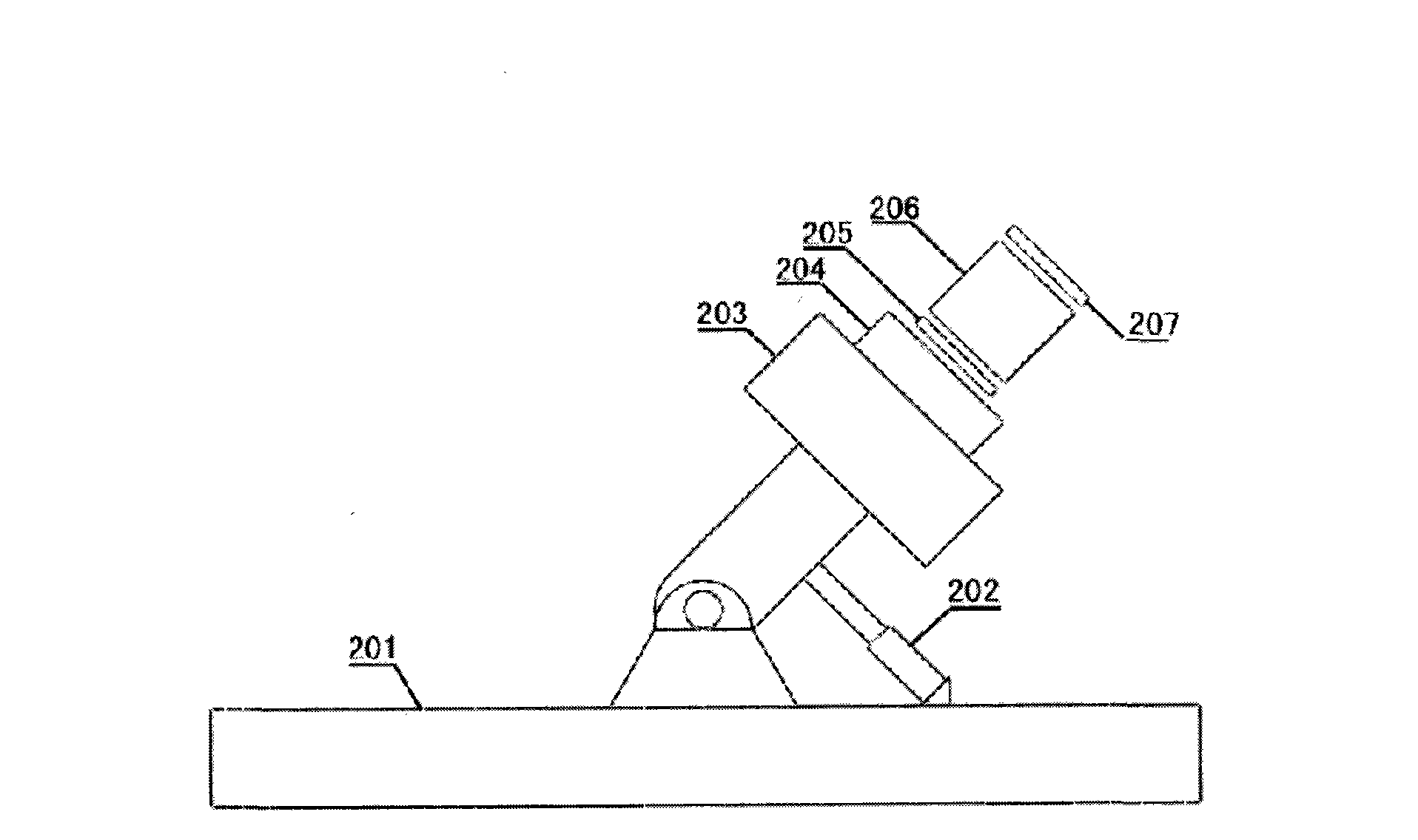
[0041] The system control and processing center controls the rotation angle of the base 201 and the lifting height of the worm screw 202 in the mechanical movement module respectively through the controller; the light intensity information obtained by the light intensity detector, and the polarization imaging module in the CCD camera 203 The acquired polarization images of the sky area are recorded and information processed in the system control and processing center.

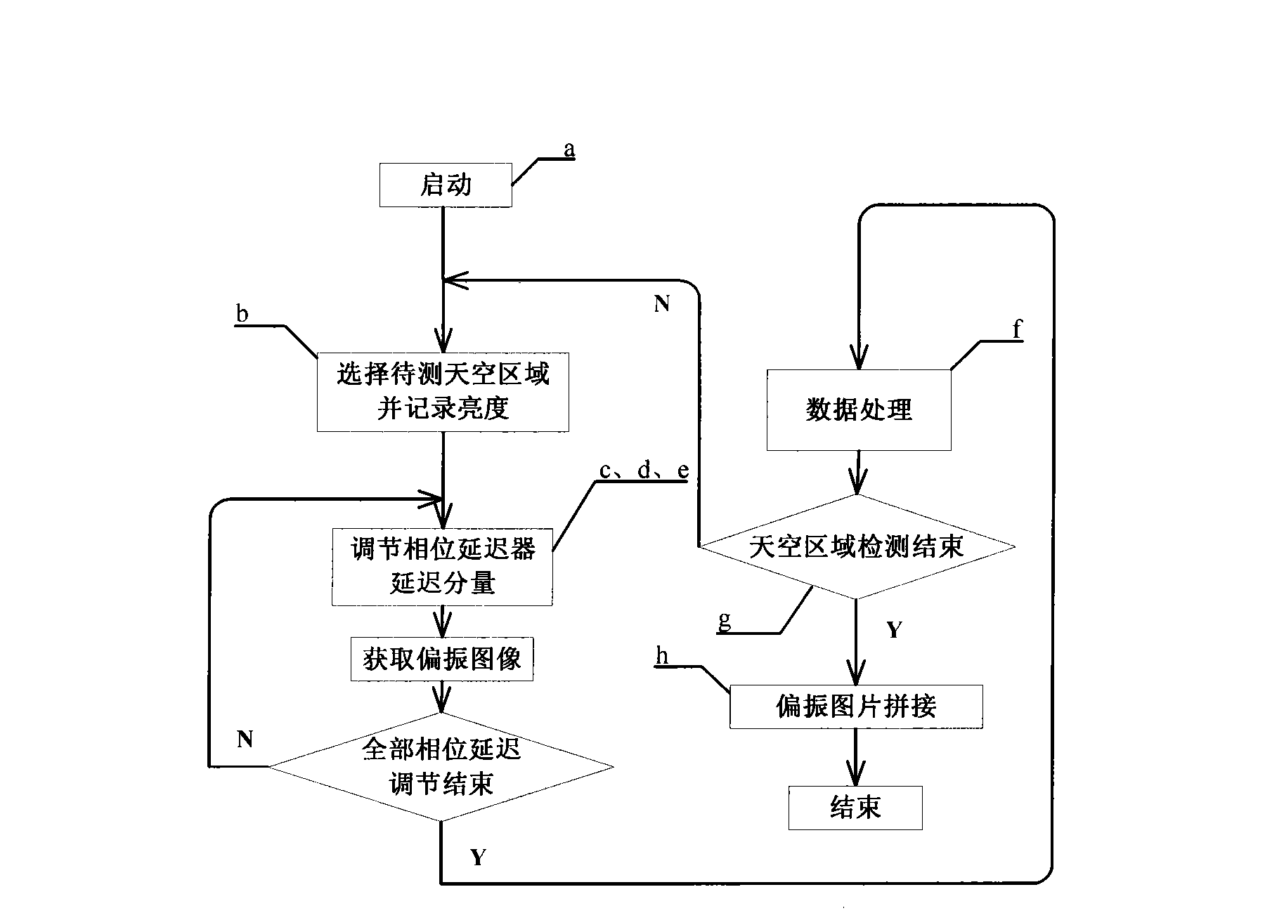
[0042] The system control and processing center is responsible for the control of the entire system and the collection, processing and storage of data. Main implementation:

[0043] 1. Control the two-dimensional movement of the mechanical movement module through the controller;

[0044] 2. Control the acquisit...


PUM


Abstract

A full automatic atmospheric polarization mode image acquisition system and a system control method are characterized in that the system comprises a polarization imaging module, a mechanical movement module, a brightness acquisition module and a system control and processing center; and the system control and processing center respectively controls the rotation angle of a base and the lift height of a worm in the mechanical movement module through a controller and records and processes the light intensity information acquired by a light intensity detector and the polarization image of sky area acquired by the polarization imaging module in a CCD camera. The invention has simple operation, accurate measurement result which is easy to calibrate, and does not need to mechanically rotate a polaroid sheet in the measurement process.

Description

technical field [0001] The invention belongs to the technical field of intelligent information acquisition and bionic robot navigation, and in particular relates to an atmospheric polarization mode image acquisition system and a system control method in bionic polarized light navigation. Background technique [0002] The surface of the earth is surrounded by a layer of atmosphere. The scattering of sunlight by the atmosphere is a very important optical phenomenon. It is the result of the interaction between light and matter. Scattering will produce polarized light. As a natural light source of transverse electromagnetic waves, sunlight is not polarized before entering the atmosphere. During the transmission process, sunlight is scattered and absorbed by air molecules and aerosol particles in the atmosphere, thus producing polarized light, and the specific polarization state distribution formed by different scattered light constitutes the atmospheric polarization mode. A kin...

Claims


Application Information

Patent Timeline
Patent Type & Authority Applications(China)
IPC IPC(8): G01J4/00G01J1/42G05B19/04
Inventor 高隽范之国吴良海崔帅潘登凯
Owner HEFEI UNIV OF TECH
Learn More