Tester for testing multifunctional vane

A test device and multi-functional technology, applied in the field of wind power blade testing, can solve the problems of only being suitable for loading from the bottom, adapting to a single type of blade, and failing to complete fatigue tests, etc., to achieve good control and adjustment performance, accurate testing, and reduced loading effect of points

Inactive Publication Date: 2009-09-23
中能风电设备有限公司
View PDF0 Cites 16 Cited by
  • Summary
  • Abstract
  • Description
  • Claims
  • Application Information

AI Technical Summary

Problems solved by technology

In order to complete the above tests, people have made various test devices, such as the test device of NREL in the United States. As for being too high, its loading method is only suitable for loading from below, and it is only suitable for the test of a single type of blade, and it is only suitable for the static strength test, and the fatigue test cannot be completed. Therefore, it is suitable for a single type of blade and a single function.
The fatigue test device of Risφ in Denmark is also only suitable for fatigue test of small-sized blades, which is suitable for single-type blades and single-function
Other test devices for blade testing are only suitable for a single model and a single function, resulting in a blade that has been tested on this test device and must be moved to another test device for testing. The test of a blade needs to be disassembled. Many times, time-consuming and labor-intensive, increasing testing costs
Moreover, a test bench is only suitable for testing a single type of blade. If a manufacturer has multiple types of blades, the number of test devices must be doubled, which greatly increases the space occupied by the test, which is time-consuming and laborious, and increases the test cost.

Method used


Image

  • Tester for testing multifunctional vane
  • Tester for testing multifunctional vane
  • Tester for testing multifunctional vane

Examples


Embodiment Construction

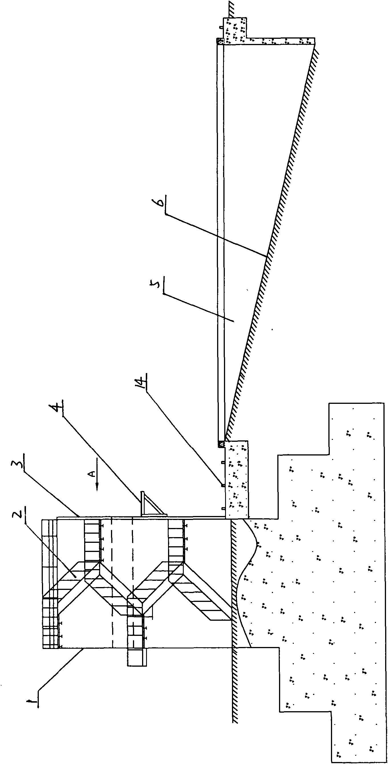
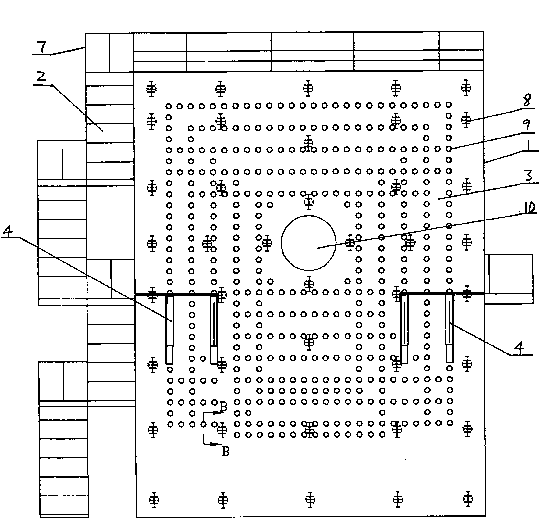
[0028] Figure 1, figure 2 , image 3 ,Figure 4 , Figure 5 , Figure 6 , Figure 7 , Figure 8 , Picture 9 , Picture 10 , Picture 11 , Picture 12 with Figure 13 As shown, this embodiment includes a test bench, a side pull loading device, and a vibration exciter.

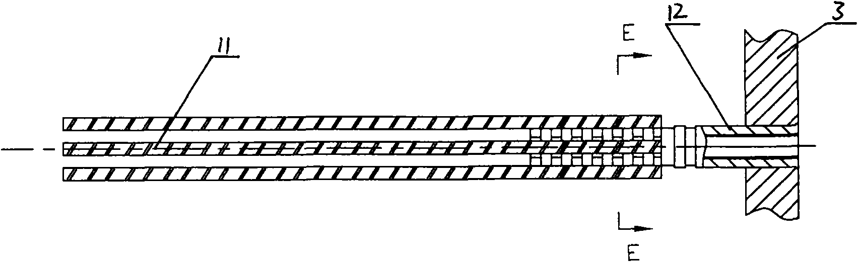
[0029] The test bench includes a table body 1, a test pit 6, and a guide rail of the side tension loading device. The platform 1 is made of reinforced concrete. The part below the ground has a stepped shape, and the front end of the part above the ground has 40 fixing parts: the blade connecting plate 3 fixed by the I-beam anchor 8. A number of blind holes 9 arranged in rows and columns are opened in the blade connecting disc 3 and the corresponding table body 1. The blind holes 9 and the I-steel anchors 8 are arranged at intervals, and the blind holes 9 are provided with blade connecting discs. 3 The bolt sleeve 12 is inlaid together, and the bolt sleeve 12 is also welded with the elongated steel bar 11 fixed in t...


PUM


Abstract

The invention discloses a tester for testing a multifunctional vane, which comprises a test bed, a tester for testing static strength and a tester for testing fatigue, wherein the bed body of the test bed is cast by reinforced concrete; the part of the test bed below ground takes the shape of a ladder; and the front end of the part of the test bed above ground is provided with a vane connecting disc fixed by a fixing part. The vane connecting disc and the bed body corresponding to the vane connecting disc are internally provided with a plurality of blind holes which are internally provided with bolt sleeves embedded with the vane connecting disc. The bolt sleeves are fixed by extension reinforcing rods fixed in the bed body. In addition, a test pit is positioned on the ground on which the front end of the bed body of the test bed is arranged; and the test pit is a slope with one end away from the bed body extending below ground. The invention has the advantages of solid structure, strong holding power and long service life. The tester has firm structure, strong supporting force and long service life, and is suitable for installation test of various vanes with different sizes, available for tests of different indexes for vanes. The tester is accurate in test, very convenient in use and wide in application range. In addition, the tester has the advantages of reducing disassembly and assembly of the vane for testing the performance index thereof, saving the testing time and cost, and reducing the damage to the vane.

Description

1. Technical Field: [0001] The invention belongs to the testing field of wind power generation blades, and particularly relates to a blade testing device. 2. Background technology: [0002] The global wind energy resource reserves are huge, about 2.74 billion megawatts, of which 20 million megawatts of wind energy can be used, which is 10 times larger than the total amount of hydropower resources on the earth, and the potential for sustainable development is huge. The wind turbine blade is the key component of the wind turbine. Its structure is extremely complex and the geometric shape is extremely irregular; the blade operation is complicated and the load is not easy to accurately determine; the raw materials used in the production of the blade have a large variety of specifications and large performance dispersion; The production process has a greater impact on the strength and quality of the blade. Therefore, the current calculation and analysis methods cannot accurately evalu...

Claims


Application Information

Patent Timeline
Patent Type & Authority Applications(China)
IPC IPC(8): G01M13/00G01M7/02G01N3/08
Inventor 易强赵晖张宁
Owner 中能风电设备有限公司
Why Eureka
Try Eureka