Method for separating metal of waste wire from plastic sheath and device thereof

A technology of waste wire and separation method, applied in circuits, electrical components, electronic waste recycling, etc., can solve the problems of incomplete separation of metal wire and plastic skin, noise pollution, tool wear, etc., to avoid wearing plastic skin and metal wire. , The effect of improving processing capacity and improving cutting efficiency

Active Publication Date: 2009-09-23
南通市通州区新志浩实业有限公司
View PDF0 Cites 10 Cited by
  • Summary
  • Abstract
  • Description
  • Claims
  • Application Information

AI Technical Summary

Problems solved by technology

So far, the copper rice machine equipment technology mainly has the following two problems: 1. The metal wire and the plastic skin are tightly combined and difficult to separate, especially the separation of the segmental metal wire and the plastic skin obtained by cutting the thin wire is more difficult. 2. During the cutting process, due to the inconsistency of the direction of the feed line, there are relatively long wire segments in the section of the cut line, and the metal wire and the plastic skin are difficult to peel off.
Therefore, in the actual process, a screen is installed at the lower part of the cutting machine, so that the long wire cannot pass through the screen, and it is cut repeatedly in the cutting machine, so that the dynamic and static knife will rub against the metal and plastic surface violently, which will not only cause severe wear of the knife, but also It also produces more metal and plastic loss and serious noise pollution, and the process consumes a lot of energy.

Method used


Image

  • Method for separating metal of waste wire from plastic sheath and device thereof
  • Method for separating metal of waste wire from plastic sheath and device thereof
  • Method for separating metal of waste wire from plastic sheath and device thereof

Examples


Embodiment 1

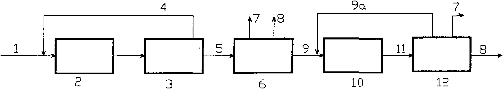
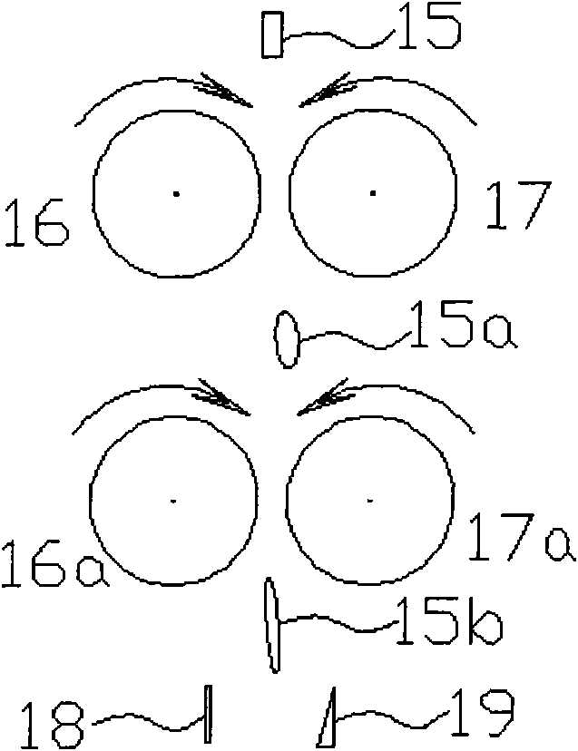
[0035] like figure 1 As shown, the waste electric wire 1 is sent to the waste electric wire cutting machine 2 and cut into short sections (the short section is 2.5mm), and then sent to the long and short section separator 3, and the long section 4 is returned to the entrance of the waste electric wire cutting machine 2. The short joints 5 separated by the long and short joint separator 3 are sent to the plastic sheath and metal wire separator 6, and the respectively separated plastic sheath 7 and metal wire 8 are discharged out of the system. The short joint 9 with the plastic sheath and the metal wire not separated is sent to the plastic sheath and metal wire stripping machine 10, and the roller rotated between the two rollers with different relative speeds deforms the plastic sheath and makes the plastic sheath and the metal wire come into contact. displacement. stripping machine such as Figure 5aAs shown, the round roller is made of stainless steel, and grooves parallel...

Embodiment 2

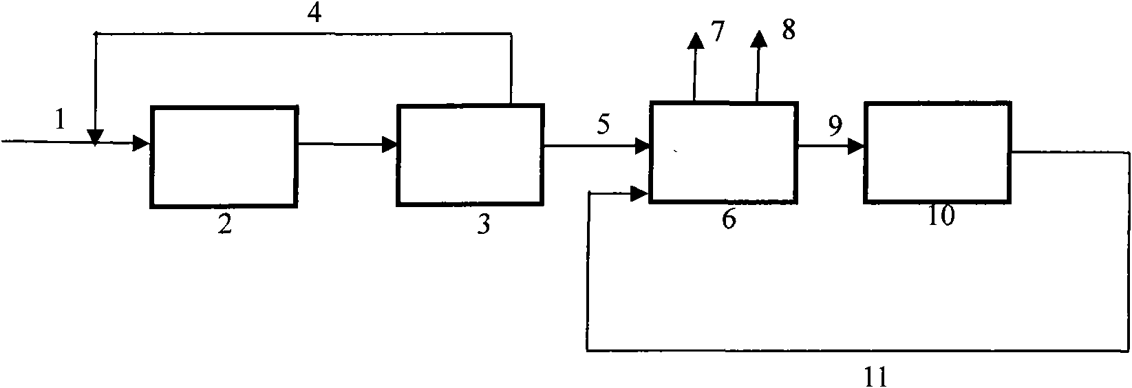
[0037] The process is the same as in Example 1. The difference is that the plastic sheath and metal wire separator 6 and the plastic sheath and metal wire separator 12 are combined into one machine to complete the separation of the plastic sheath and the metal wire. like figure 1 As shown, the plastic sheath and metal wire stripping machine 10, the discharged material is returned to the plastic sheath and metal wire separator 6 for separation again.

Embodiment 3

[0039] The process is the same as in Example 2. The difference is that the plastic sheath and the metal wire stripping machine 10 are adopted as Figure 4 Shown disc 13 and round roller 14 form the disc-roller peeling machine, and the round roller and disc that are rotated between a roller and a disc with different relative linear speeds deform the plastic skin, and make the plastic skin bond with the metal The relative displacement of the wire occurs, and the stripping machine such as Figure 5b As shown, grooves inclined to the axial direction are formed on the round roller, and non-concentric grooves are also formed on the disk (not shown in the figure).


PUM


Abstract

The invention relates to a method for separating a metal of a waste wire from a plastic sheath and a device thereof. The method at least comprises the following steps: the waste wire is cut into several sections; the cut wires are divided into long sections and short sections; the wires with long sections are returned to the inlet of a cutting process so as to be cut again; the metal wires of the wires with short sections are separated from the plastic sheaths thereof; the metal wires of the unpeeled wires with short sections are separated from the plastic sheaths thereof again; and plastic sheaths of the peeled wires are separated from the rubber-insulated wires of the metal wires. The invention improves cutting efficiency since a cutter has high cutting efficiency with out a screen mesh and the wires with long sections are returned to be cut, simultaneously greatly reduces power consumption, and improves the processing capability of machines. Two motion bodies with different relative velocity are used for peeling the unpeeled wire sections so as to lead the plastic sheath to be deformed and the plastic sheath to move relatively to the metal wire, and lay the foundation for subsequent separation.

Description

technical field [0001] The invention relates to a separation process method and device for metal and plastic sheaths of waste electric wires, belonging to the technical field of solid waste treatment and recycling, especially electronic waste recycling. Background technique [0002] With the advancement of technology and economic development, the amount of electric wires has increased significantly, and the amount of waste has also increased sharply. Wires are rich in copper and other non-ferrous metals and plastics, which are valuable resources. However, the two are closely connected and difficult to separate, and improper handling will pollute the environment. At present, the recycling of resources in waste cables (such as metal copper, aluminum, iron, and non-metallic plastics, rubber, etc.) mostly adopts mechanical methods, and the main processing equipment is peeling machine and copper rice machine. When the diameter of the metal conductor in the waste cable is large,...

Claims


Application Information

Patent Timeline
IPC IPC(8): H01B15/00
CPCY02W30/82
Inventor 张书廷
Owner 南通市通州区新志浩实业有限公司
Why Eureka
Try Eureka