Method for compensating network node crystal oscillation frequency error of wireless sensor
A wireless sensor, crystal oscillator frequency technology, applied in the field of sensor network clock synchronization, can solve problems such as increasing cost and inability to eliminate errors, and achieve the effects of reducing power consumption, improving accuracy, and reducing communication overhead
Inactive Publication Date: 2011-01-05
ELECTRIC POWER RES INST OF STATE GRID ANHUI ELECTRIC POWER +2
View PDF0 Cites 2 Cited by
- Summary
- Abstract
- Description
- Claims
- Application Information
AI Technical Summary
Problems solved by technology
However, the temperature / frequency curve must be measured before leaving the factory, which will increase the cost during mass production and cannot eliminate the error caused by aging
Method used
View moreImage
Smart ImageViewing Examples
Examples
Embodiment 1
Embodiment 2
Embodiment 3
Login to View More PUM
 Abstract
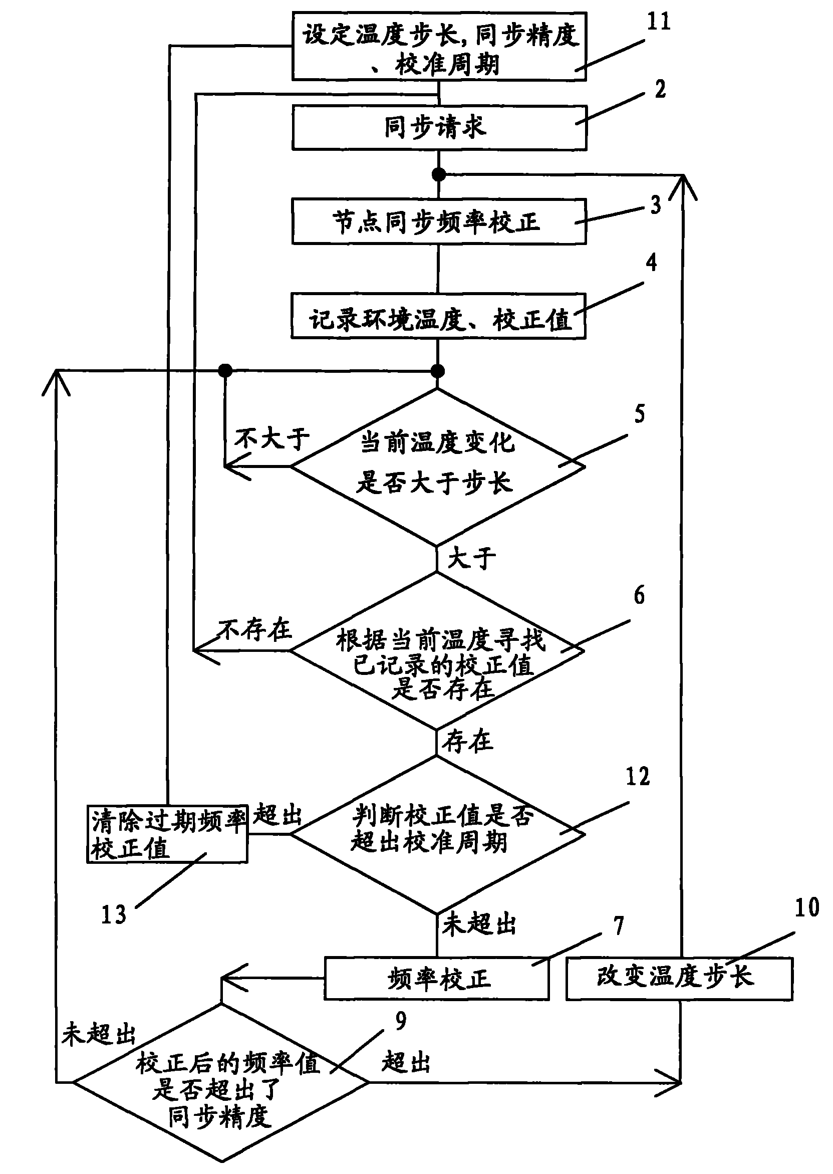
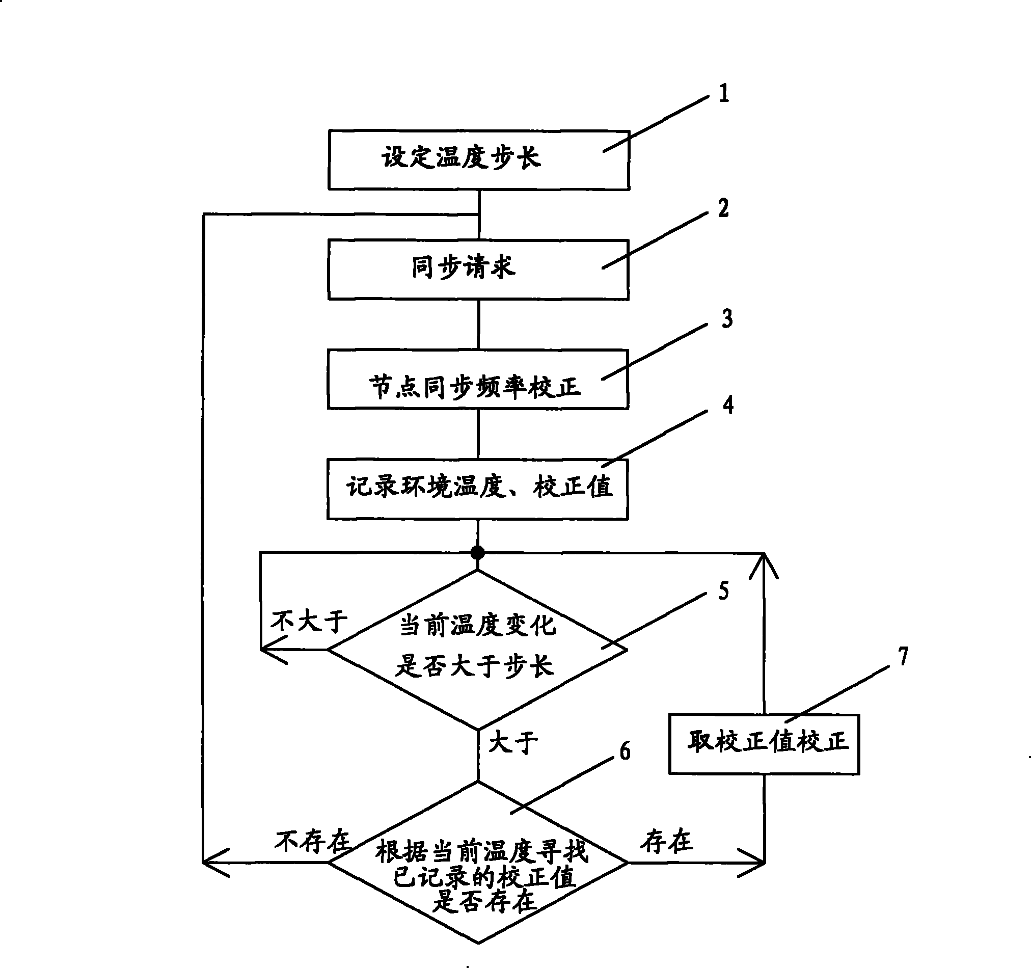
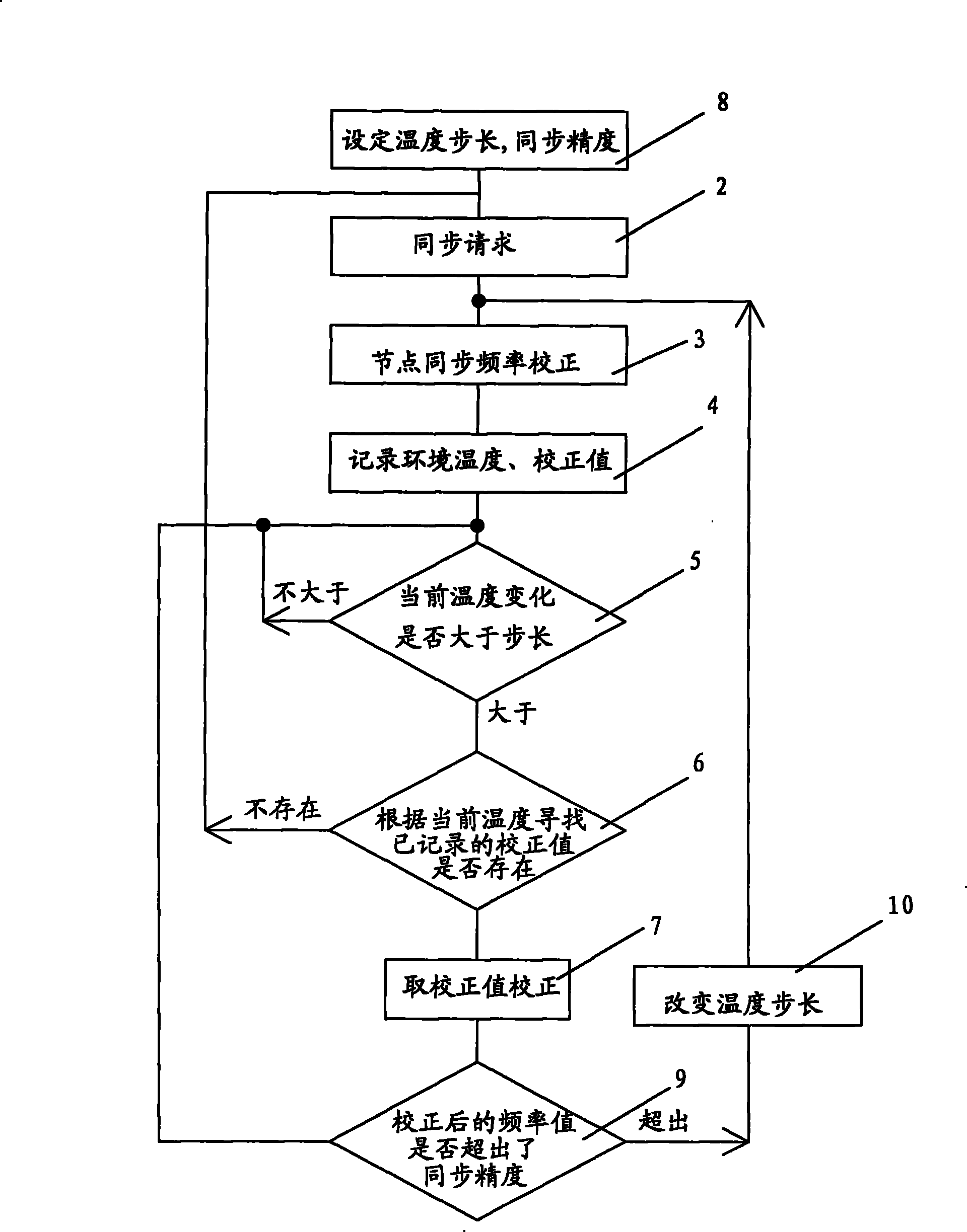
The invention relates to a method for compensating a network node crystal oscillation frequency error of a wireless sensor. The method is realized by the network server and network nodes of the wireless sensor, and comprises the steps: temperature step length, crystal oscillation synchronous accuracy and crystal oscillation aging calibrating period are set; a datasheet including synchronous environmental temperature and the corresponding correct value with different frequencies is set up; synchronous frequency automatic correction is carried out on the node crystal oscillation according to the change of the environmental temperature. The method has the advantages that 1. in the long-time monitoring process, after the datasheet is set up, crystal oscillation regulating synchronous command is not needed; 2. the accuracy is improved, and the energy consumption is reduced; 3. temperature compensation calibration is carried out without leaving factory, and the temperature is unrelated to aging rate when the synchronous requirement of the wireless sensor is met; 4. as no frequent divergent crystal oscillation synchronous command is required, the communication cost is reduced, the power consumption is lowered, and the method is suitable for monitoring large scale of network nodes in wireless network for a long time; 5. the transient variation of temperature can be corrected in time.
Description
Compensation Method for Frequency Error of Crystal Oscillator in Wireless Sensor Network Nodes technical field The invention relates to a sensor network clock synchronization technology, a method for correcting temperature changes and aging of node clock crystal oscillators in a wireless sensor network system, and in particular to a wireless sensor network node crystal oscillator frequency error compensation method. Background technique Wireless sensor networks are considered to be one of the important emerging technologies in the 21st century. Clock synchronization technology is a key technology of wireless sensor network. The operation of its own protocol and the application based on it all require the clocks of nodes in the network to be synchronized. The main purpose of traditional clock synchronization technology is how to obtain high-precision time synchronization. However, the purpose of clock synchronization of each node in the sensor network is to reduce the com...
Claims
Login to View More Application Information
Patent Timeline
 Patent Type & Authority Patents(China)
IPC IPC(8): H04L7/00H04W56/00
CPCY02B60/50Y02D30/70
Inventor 汪江杜晓峰田万军陈自年刘云涛
Owner ELECTRIC POWER RES INST OF STATE GRID ANHUI ELECTRIC POWER
Features
- R&D
- Intellectual Property
- Life Sciences
- Materials
- Tech Scout
- Unparalleled Data Quality
- Higher Quality Content
- 60% Fewer Hallucinations
Learn More Browse by: Latest US Patents, China's latest patents, Technical Efficacy Thesaurus, Application Domain, Technology Topic, Popular Technical Reports.
© 2025 PatSnap. All rights reserved.Legal|Privacy policy|Modern Slavery Act Transparency Statement|Sitemap|About US| Contact US: help@patsnap.com


