Liquid ejecting head, liquid ejecting apparatus, and actuator

A liquid ejection head and liquid ejection technology, which can be used in printing and other directions to solve problems such as the destruction of the taper portion of the piezoelectric layer

Inactive Publication Date: 2009-09-30
SEIKO EPSON CORP
View PDF3 Cites 2 Cited by
  • Summary
  • Abstract
  • Description
  • Claims
  • Application Information

AI Technical Summary

Problems solved by technology

[0004] For example, in the structure described in Patent Document 2, although the upper electrode is not formed on the portion (hereinafter referred to as the tapered portion) that is the inclined surface of the piezoelectric layer, the lower electrode is continuous across the plurality of piezoelectric elements. Therefore, a strong driving electric field will act on the tapered part of the piezoelectric layer, which may cause the tapered part of the piezoelectric layer to be damaged

Method used


Image

  • Liquid ejecting head, liquid ejecting apparatus, and actuator
  • Liquid ejecting head, liquid ejecting apparatus, and actuator
  • Liquid ejecting head, liquid ejecting apparatus, and actuator

Examples


Embodiment approach 1

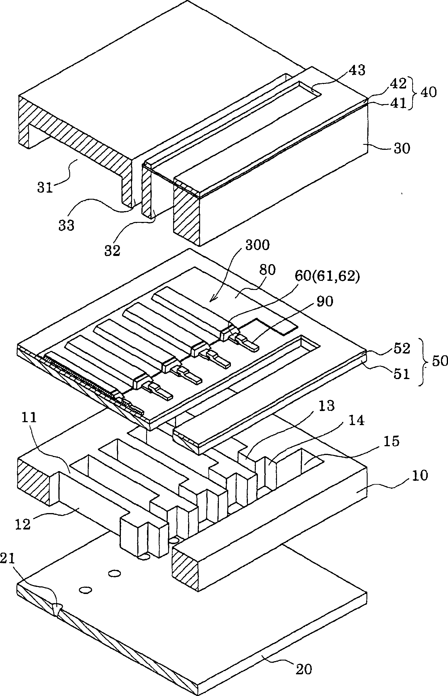
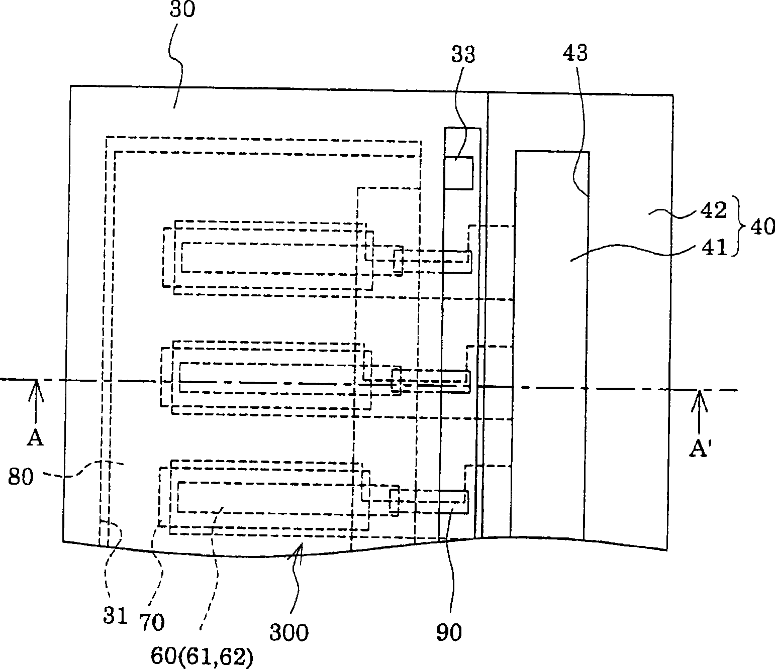
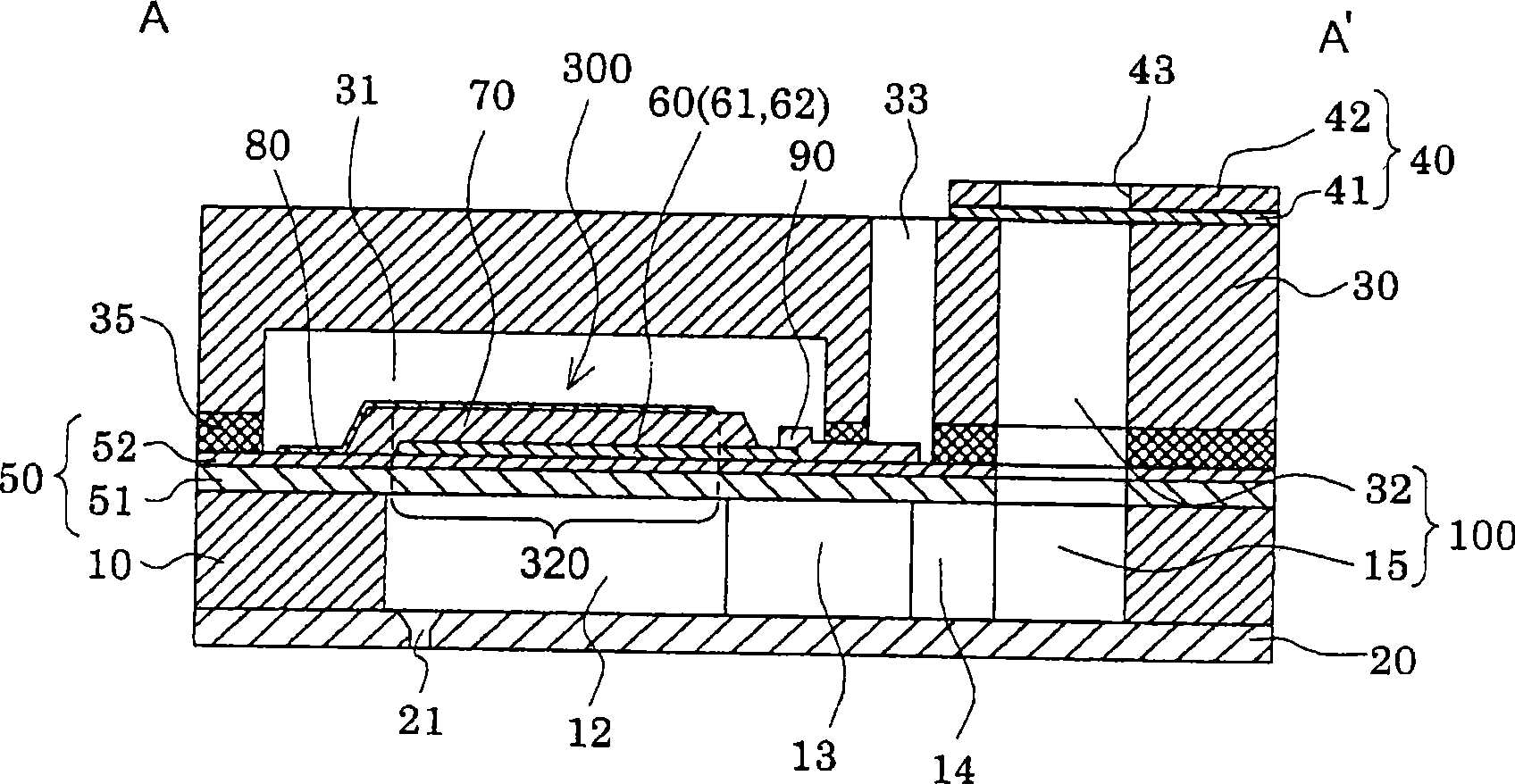
[0041] figure 1 It is an exploded perspective view showing a schematic structure of an ink jet recording head which is an example of the liquid ejecting head according to Embodiment 1 of the present invention, Figure 2A and Figure 2B respectively figure 1 The plan view and the A-A' sectional view of the plan view.

[0042] As shown in the figure, the channel forming substrate 10 is formed of a single crystal silicon substrate having a crystal plane direction of (110) in this embodiment, and an elastic film 51 made of an oxide film is formed on one surface thereof. On the flow path forming substrate 10 , a plurality of pressure generating chambers 12 divided by the partition wall 11 and having one surface formed of an elastic film 51 are arranged side by side in the width direction thereof.

[0043] On one end side in the longitudinal direction of the pressure generating chambers 12 on the flow path forming substrate 10 , an ink supply passage 13 and a communication path 1...

Embodiment approach 2

[0084] Figure 8 It is a cross-sectional view showing main parts of the ink jet recording head according to the second embodiment.

[0085] This embodiment is another example of the structure of the lower electrode film, and the structure other than the lower electrode film 60 is the same as that of the first embodiment. That is, compared to the formation of the orientation control layer 62 on the conductive layer 61 (upper surface) in Embodiment 1, as Figure 8 As shown, in this embodiment, the orientation control layer 62A constituting the lower electrode film 60 is provided on the upper surface and the end surface of the conductive layer 61 , that is, the orientation control layer 62A is provided to cover the conductive layer 61 .

[0086] With such a structure, since piezoelectric layer 70 is formed on orientation control layer 62A also at the end surface of lower electrode film 60 , the crystallinity of piezoelectric layer 70 near the end of lower electrode film 60 is fu...

Embodiment approach 3

[0088] Figure 9 is an exploded perspective view showing a schematic configuration of an ink jet recording head according to Embodiment 3, Figure 10A and Figure 10B respectively Figure 9 and the BB' section of the plan. in addition, Figure 11 It is a cross-sectional view showing main parts of the ink jet recording head according to the third embodiment. for with Figure 1 ~ Figure 3 Components that are the same as those shown are assigned the same reference numerals and repeated explanations are omitted.

[0089] This embodiment is the same as Embodiment 1 except that the common electrode of the piezoelectric element 300 is formed of the lower electrode film 60A constituting the piezoelectric element 300 and the dedicated electrode is formed of the upper electrode film 80A.

[0090] As shown in the figure, the lower electrode film 60A of the present embodiment is provided on each area opposite to each pressure generating chamber 12 with a width narrower than that of th...


PUM


Abstract

The invention provides a liquid ejecting head, a liquid ejecting apparatus and an actuator capable of improving shift characteristics of piezoelectric element and preventing the piezoelectric layer from damage. A end face of a piezoelectric layer (70) is composed of inclined planes in a incline mode of end of a lower electrode side is outsider than a upper electrode side. The lower electrode (60) for composing piezoelectric elements has a width smaller than the width of the pressure generating chambers (12). The piezoelectric layer (70) has a larger width than the lower electrode (60) to cover end faces of the lower electrode (60). The vibration plate (50) has a top layer formed of a titanium oxide insulator film (52). The lower electrode has a top layer formed of a lanthanum nickel oxide orientation control layer (62). The orientation control layer (62) and at least part of the piezoelectric layer (70a) disposed on the orientation control layer (62) are formed of perovskite crystals having a (111) preferred orientation.

Description

technical field [0001] The present invention relates to a liquid ejection head that ejects liquid droplets from a nozzle by displacement of a piezoelectric element, a liquid ejection device, and an actuator having a piezoelectric element. Background technique [0002] Among the ink jet type recording heads as a representative example of the liquid ejection head that ejects liquid droplets, some ink jet type recording heads have, for example, a piezoelectric element formed by a flow chamber formed with a pressure generating chamber via a vibrating plate. The inkjet type recording head is composed of a lower electrode, a piezoelectric layer, and an upper electrode on one side of a path-forming substrate, and the displacement of the piezoelectric element applies pressure to the pressure generating chamber, thereby ejecting ink droplets from the nozzles. . It is known that the displacement characteristics of piezoelectric elements used in such ink jet recording heads vary great...

Claims


Application Information

Patent Timeline
Patent Type & Authority Applications(China)
IPC IPC(8): B41J2/14
Inventor 岛田胜人
Owner SEIKO EPSON CORP
Why Eureka
Try Eureka