Pressure control valve
A pressure control and spool technology, applied in the field of pressure control valves, can solve the problems of compressor shutdown, cooling capacity reduction, compressor capacity reduction, etc., and achieve the effect of good reliability and shock avoidance
- Summary
- Abstract
- Description
- Claims
- Application Information
AI Technical Summary
Problems solved by technology
Method used
Image

Examples
Embodiment 1
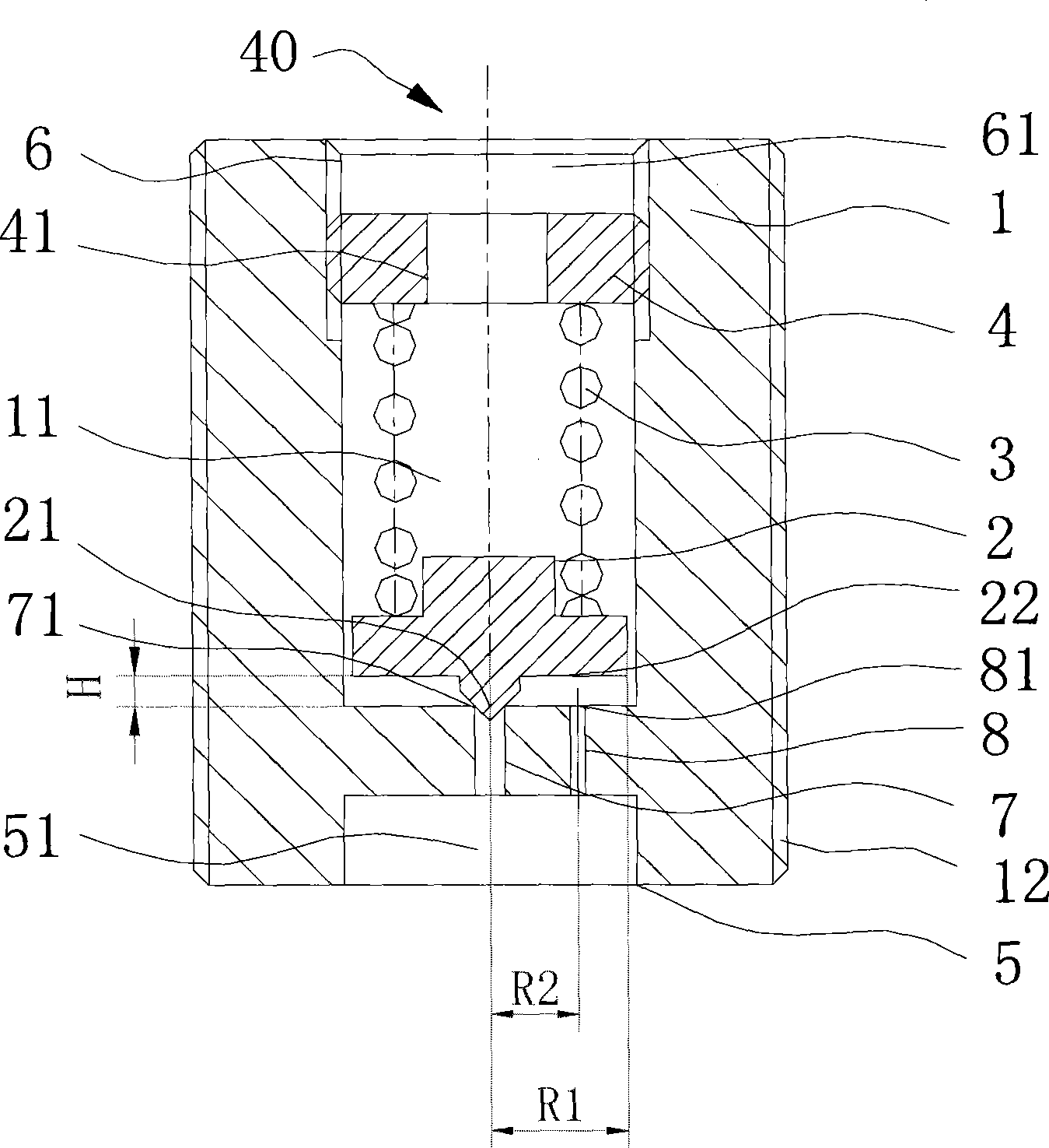
[0056] This embodiment combines Figure 2 ~ Figure 4 A specific embodiment of the pressure control valve will be described.
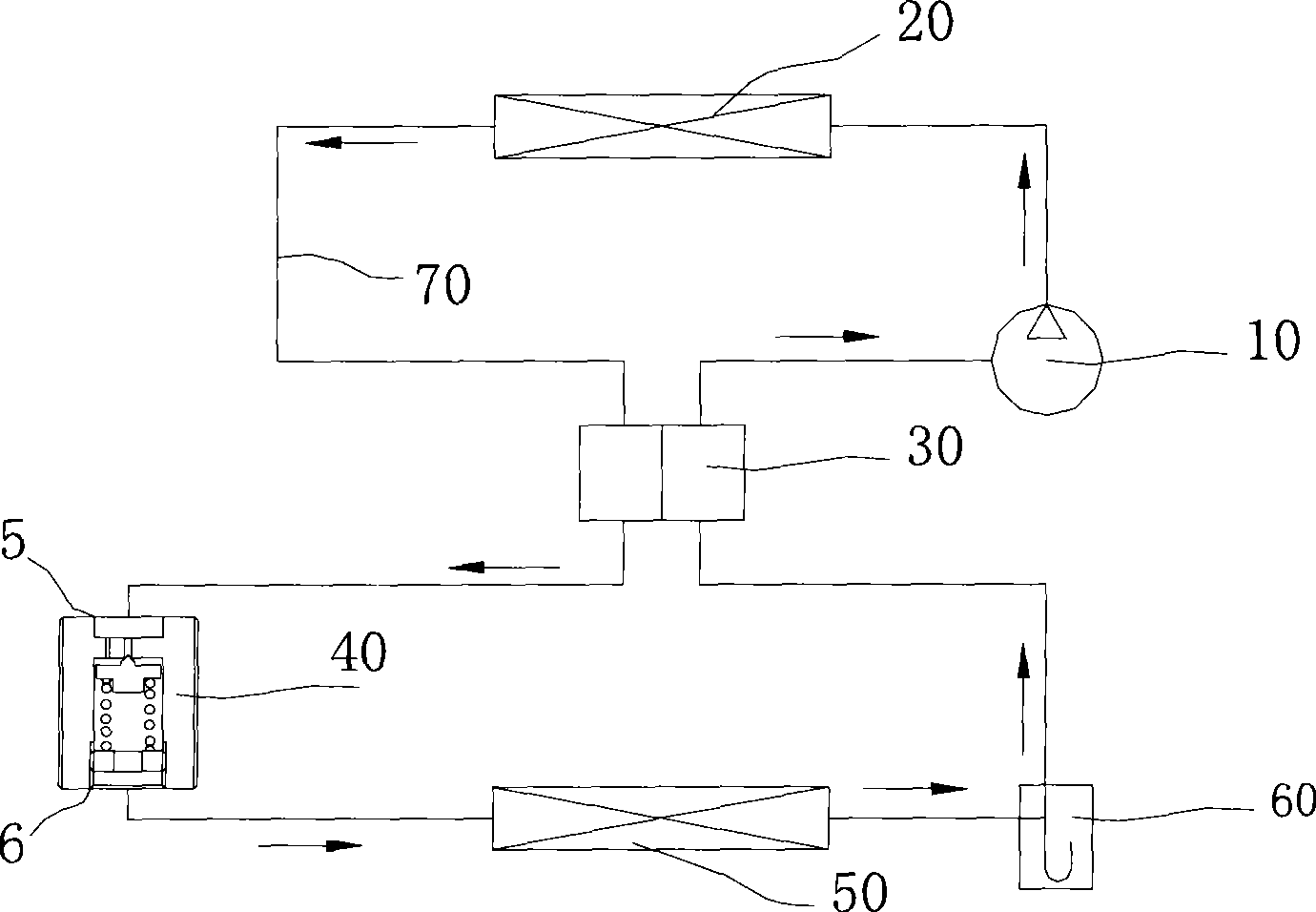
[0057] figure 2 It is a schematic diagram of the structure of the pressure control valve described in Embodiment 1. Such as figure 2 As shown, the pressure control valve includes: a valve body 1; a low-pressure chamber 61, an inner cavity 11 of the valve body 1, and a high-pressure chamber 51 arranged in sequence; end, the inner chamber 11 is located between them, and a throttling passage 7 is provided between the inner chamber 11 and the high-pressure chamber 51, and the throttling passage 7 has a valve port 71 facing the inner chamber 11; the high-pressure chamber 51 The high pressure port 5 is connected to the outlet side of the cooler 20 through the heat exchanger 30, while the low pressure port 6 of the low pressure chamber 61 is connected to the inlet side of the evaporator 50;
[0058] Between the low-pressure chamber 61 and the inner cavit...
Embodiment 2
[0070] The following is attached Figure 5 and Figure 6 A preferred embodiment of the present invention is disclosed. Figure 5 is a structural schematic diagram of the pressure control valve described in this embodiment, Figure 6 yes Figure 5 Side view along direction A.
[0071] Such as Figure 5 As shown, similar to Embodiment 1, the pressure control valve described in this embodiment includes: a valve body 1; a low-pressure chamber 61, an inner chamber 11 of the valve body 1 and a high-pressure chamber 51 arranged in sequence, and the inner chamber 11 and The low-pressure chamber 61 is communicated with the passage 41, and the inner chamber 11 communicates with the high-pressure chamber 51 through the throttling passage 7; The valve port 71 toward the inner chamber 11 moves back and forth, so that the valve port 71 is opened or closed, and the degree of opening and closing of the valve core changes with the pressure of the high-pressure chamber 51; it also includes...
Embodiment 3
[0078] This embodiment combines the attached Figure 7 Another embodiment of the pressure control valve according to the present invention is disclosed.
[0079] Figure 7 is a structural schematic diagram of the pressure control valve described in this embodiment, such as Figure 7 As shown, the difference from the pressure control valves in the aforementioned Embodiment 1 and Embodiment 2 is that in this embodiment, the axes of the high-pressure chamber 51 and the low-pressure chamber 61 are perpendicular to each other, and the axis of the normally open throttling passage 8" It intersects with the axis of the spool 2 and the included angle is R. The other structures are similar to those in Embodiment 1 and will not be repeated here.
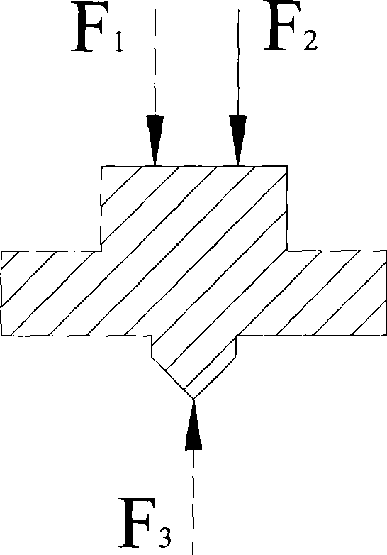
[0080] Under normal conditions, the refrigerant pressure F1 in the inner cavity 11 of the valve core 2 and the thrust F2 of the spring 3 close the throttling passage 7, and the refrigerant pressure in the high-pressure chamber 51" exerts a fo...
PUM
| Property | Measurement | Unit |
|---|---|---|
| The inside diameter of | aaaaa | aaaaa |
Abstract
Description
Claims
Application Information
 - Generate Ideas
- Intellectual Property
- Life Sciences
- Materials
- Tech Scout
- Unparalleled Data Quality
- Higher Quality Content
- 60% Fewer Hallucinations
Browse by: Latest US Patents, China's latest patents, Technical Efficacy Thesaurus, Application Domain, Technology Topic, Popular Technical Reports.
© 2025 PatSnap. All rights reserved.Legal|Privacy policy|Modern Slavery Act Transparency Statement|Sitemap|About US| Contact US: help@patsnap.com