
High-efficiency energy-saving emission-reduction circulating fluid bed organic heat carrier boiler

A circulating fluidized bed, high-efficiency and energy-saving technology, applied in fluidized bed combustion equipment, fluid heaters, indirect carbon dioxide emission reduction, etc., can solve the problems of high investment in dust removal equipment, high requirements for coal-fired coal types, and low utilization rate of waste heat, etc. problem, to achieve the effect of solving the problem of single fuel type, protecting the environment and saving energy

Inactive Publication Date: 2009-09-30
SHANDONG SHENGWEI BOILER
View PDF0 Cites 12 Cited by
  • Summary
  • Abstract
  • Description
  • Claims
  • Application Information

AI Technical Summary

Problems solved by technology

[0003] The purpose of the present invention is to solve the problems of existing organic heat carrier boilers, such as severe heating surface wear, low coal combustion rate, high coal type requirements, serious environmental pollution, high investment in dust removal equipment, high operating costs, and low utilization rate of waste heat. problem, to provide a high-efficiency, energy-saving and emission-reducing circulating fluidized bed organic heat carrier boiler to overcome the deficiencies in the prior art

Method used

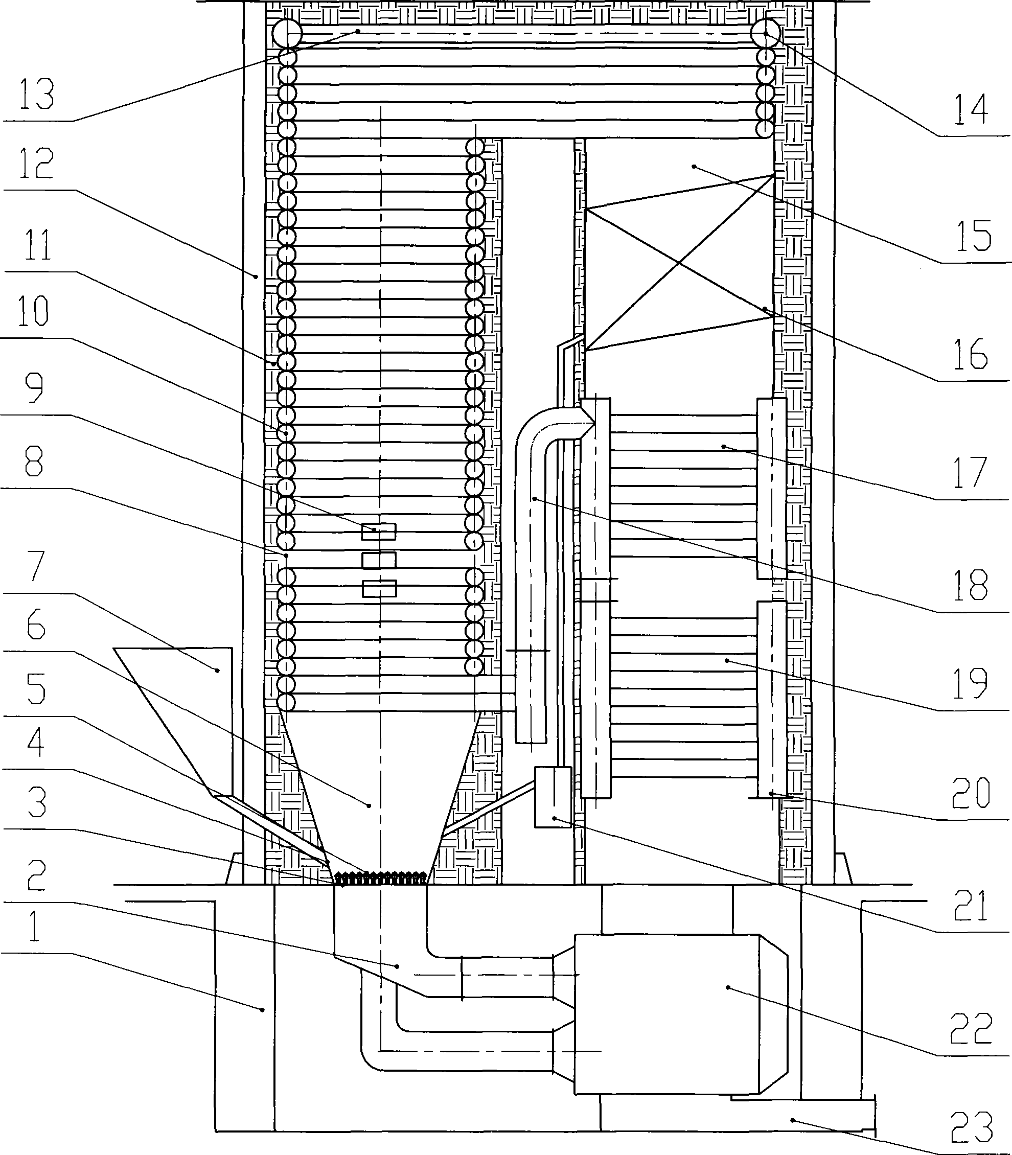
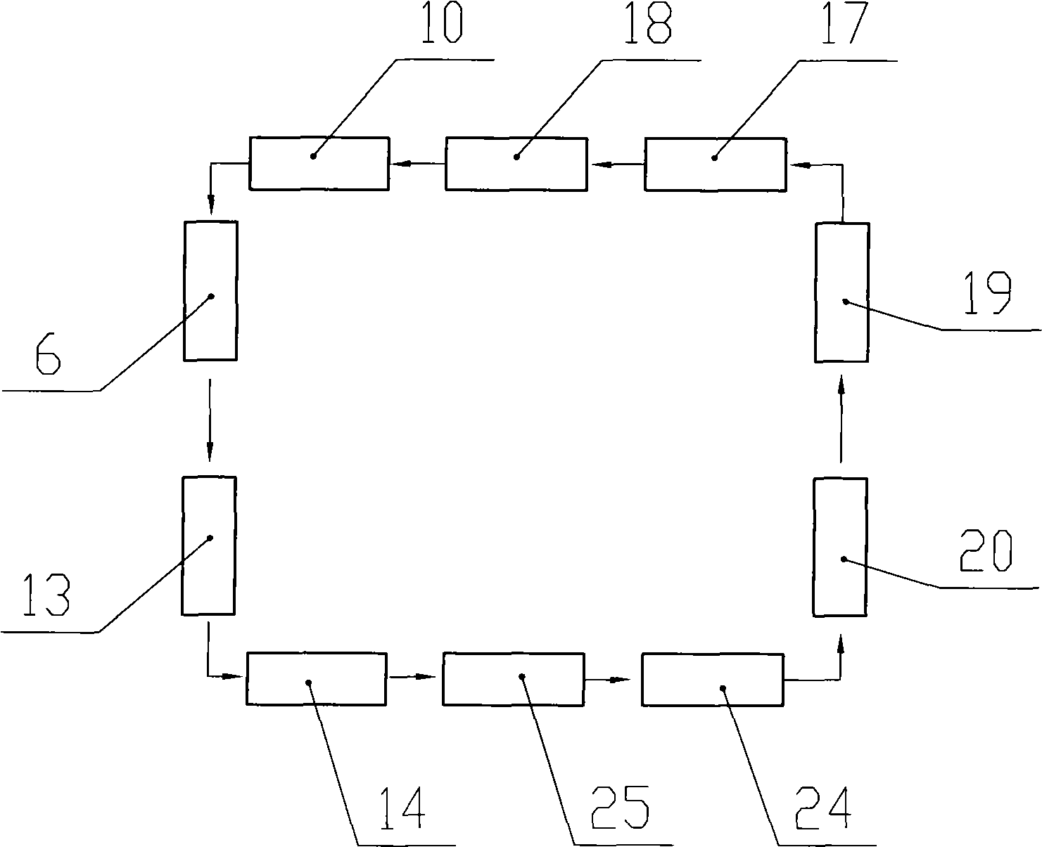
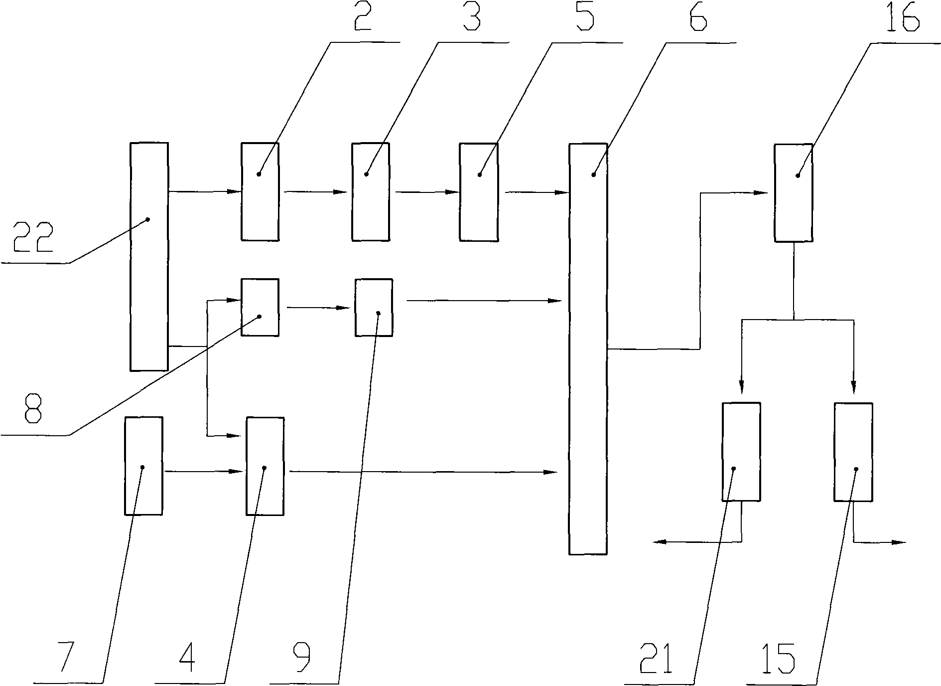

Image

  • High-efficiency energy-saving emission-reduction circulating fluid bed organic heat carrier boiler
  • High-efficiency energy-saving emission-reduction circulating fluid bed organic heat carrier boiler
  • High-efficiency energy-saving emission-reduction circulating fluid bed organic heat carrier boiler

Examples


Embodiment Construction

[0016] refer to figure 1 , figure 2 , image 3 and Figure 4 , the present invention includes a boiler base 1, a coal hopper 7 and a heat medium circulation pump 24. A furnace body composed of a steel frame 12 and a heat-preservation refractory layer 11 is arranged on the top of the boiler base 1 from the outside to the inside. The furnace 6 and the flue 15; the upper part of the furnace 6 is provided with a top heating surface 13, a square plate radiation heating tube bundle 10, a secondary air nozzle 9 is provided in the gap 8 of the coil tubes, and a cloth is arranged at the bottom of the furnace 6. The air plate 3 and the air distribution plate 3 are provided with a wind cap 5, the furnace 6 is connected with the coal hopper 7 through the coal supply pipe 4, and the bottom of the furnace 6 is provided with an equal pressure air box 2; the flue 15 is provided with an outlet set from top to bottom Box 14, cyclone separator 16 and interconnected high temperature convectio...


PUM


Abstract

The invention discloses a high-efficiency energy-saving emission-reduction circulating fluid bed organic heat carrier boiler which comprises a boiler base, a coal scuttle and a heat medium circulation pump, wherein a boiler body formed by steel racks and insulation fire-resistant layers from outside to inside is arranged on the upside of the boiler base; a hearth and a flue the top parts of which are communicated are arranged in the boiler body in parallel; a top part heating surface and a square plate radiation heating pipe bundle are arranged on the upper part of the hearth from top to bottom; a secondary wind nozzle is arranged in a clearance of coil pipes; the lower part of the hearth is provided with a grid plate, a wind cap and an equipressure wind box; the flue is sequentially provided with an outlet container, a cyclone separating device, a high-temperature convection pipe bundle, a low-temperature convection pipe bundle and an air preheater; the flue is communicated with a smoke outlet arranged on the underside through the air preheater; the cyclone separating device is communicated with the hearth by a pipeline through a back feeder; the high-temperature convection pipe bundle is communicated with the square plate radiation heating pipe bundle by a middle linkage box; the low temperature convection pipe bundle is communicated with the heat medium circulation pump; and the heating surface is communicated with a heat device by the outlet container. The invention protects the environment, saves energy and has long service life.

Description

technical field [0001] The invention belongs to the technical field of organic heat carrier boilers, and relates to a circulating fluidized bed organic heat carrier boiler with high efficiency, energy saving and emission reduction. Background technique [0002] At present, my country's organic heat carrier boilers are mainly coal-fired, adopting a layered combustion method, and the combustion equipment is in the form of fixed hand-fired furnaces, chain furnaces, reciprocating furnaces, and vibration furnaces. The existing circulating fluidized bed boilers are in the furnace A separator is added at the exit to collect part of the soot and return it to the furnace for combustion. The boiler with this structure has a large concentration of circulating soot, serious wear on the heating surface, low coal combustion rate, high requirements for coal types, serious environmental pollution, and dust removal. Technical problems such as high equipment investment, high operating cost, and...

Claims


Application Information

Patent Timeline
Patent Type & Authority Applications(China)
IPC IPC(8): F24H7/00F23C10/10F23L15/00
CPCY02E20/34
Inventor 李守泉刘福涛景怀岚徐雷李博陈立杨洪良孙华臻鲍红刘乐泉
Owner SHANDONG SHENGWEI BOILER
Learn More