Composite oil gas separation method and composite oil gas separator

A technology of oil-gas separator and separation method, which is applied in the direction of machines/engines, swirl devices, crankcase ventilation, etc., which can solve the problems of high-efficiency oil-gas separation, achieve high-efficiency separation, high cost performance, and avoid flow short-circuit effects

Inactive Publication Date: 2009-10-07
JILIN UNIV
View PDF0 Cites 33 Cited by
  • Summary
  • Abstract
  • Description
  • Claims
  • Application Information

AI Technical Summary

Problems solved by technology

[0004] The purpose of the present invention is to provide a compound oil-gas separation method and a compound oil-gas separator to solve the problem of high-efficiency oil-gas separation under all working conditions of the internal combustion engine

Method used


Image

  • Composite oil gas separation method and composite oil gas separator
  • Composite oil gas separation method and composite oil gas separator

Examples


Embodiment Construction

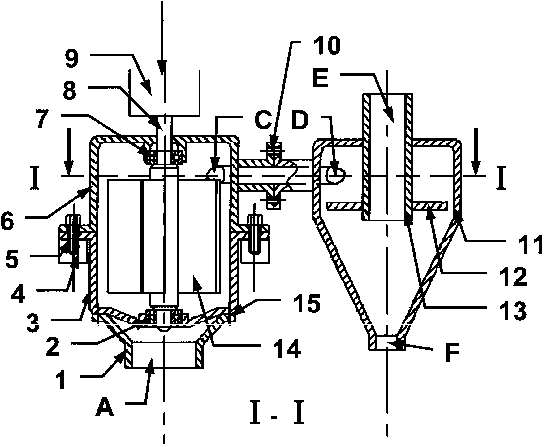
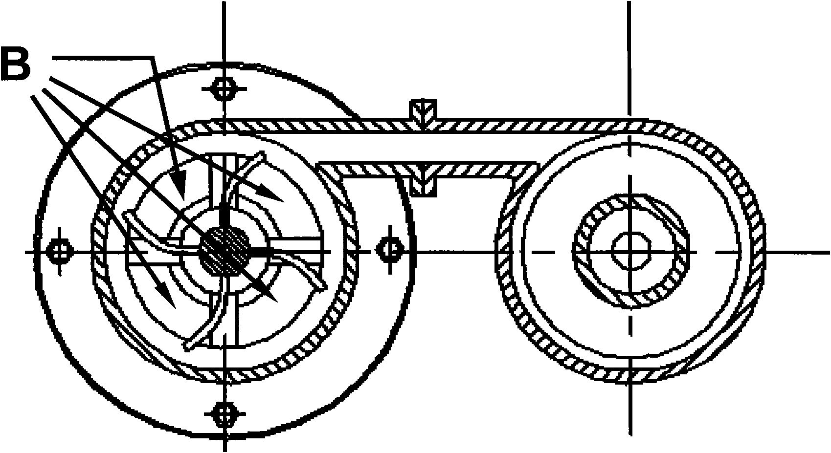
[0023] Below in conjunction with the example shown in the accompanying drawings, further illustrate the specific content of the present invention and its working process.

[0024] A compound oil-gas separation method combining active and passive centrifugal separation principles. Among them, the active centrifugal separator drives the transmission shaft 8 through the external power source 9, drives the blades 14 to rotate, sucks the crankcase blow-by gas into the separation chamber, and controls the speed of the transmission shaft 8 in a closed loop according to the variation of the crankcase blow-by gas with the working conditions of the internal combustion engine , to achieve high-efficiency separation of oil and gas under all working conditions, and to maintain the crankcase pressure within the set range. The pressurized and accelerated exhaust gas enters the passive cyclone separator along the tangential direction, which improves the separation efficiency and makes up for t...


PUM


Abstract

The present invention relates to a method and a device for separating liquid or solid particles in air flow, especially to a composite oil gas separation method applied to the crankcase blow-by of internal combustion engine and a composite oil gas separator. The method adopts a mode of combining an active centrifugal type separation and a passive cyclone type separation for separating. The device is mainly composed of an active centrifugal type separator and a passive cyclone type separator. The active centrifugal type separator adopts a one-stage separation. The passive cyclone type separator adopts a two-stage separation. The air outlet (C) of active centrifugal type separator is communicated with the gas tangential inlet (D) of passive cyclone type separator. The center of separation chamber of passive cyclone type separator is installed with an exhaust insertion tube (13) for forming a gas outlet (E) of passive cyclone type separator. The lower end of separation chamber of passive cyclone type separator is installed with an engine oil outlet (F) communicated with the crankcase. The method and the device of the invention have the characteristics of high separation efficiency and suitability for the changing of blow-by along with the work condition.

Description

technical field [0001] The invention relates to a device for separating engine oil or solid particles in gas flow, in particular to an oil-gas separator for crankcase gas of an internal combustion engine. Background technique [0002] With the increasingly stringent automobile emission regulations and the continuous adoption of new technologies, they all require the efficient separation of oil and gas from the crankcase blow-by gas of internal combustion engines. During the compression and power stroke of the internal combustion engine, part of the high-pressure gas in the cylinder escapes into the crankcase through the end gap of the piston ring, the side gap between the piston ring and the ring groove, and the gap between the piston ring and the cylinder wall. And the state changes, and gradually increase the crankcase pressure; because the crankcase is connected to the oil pan, under the action of high temperature and splashing, the oil mist oil is involved in the blow-by...

Claims


Application Information

Patent Timeline
Patent Type & Authority Applications(China)
IPC IPC(8): B04C9/00F01M13/04
Inventor 高莹李君朱昌吉杨世春孙巍
Owner JILIN UNIV
Why Eureka
Try Eureka