Laser three-dimensional preparing method of non-spherical micro-lens
A laser three-dimensional, micro-lens technology, applied in the field of micro-manufacturing, can solve problems such as difficult to apply to the preparation of micro-optical components
- Summary
- Abstract
- Description
- Claims
- Application Information
AI Technical Summary
Problems solved by technology
Method used
Image
Examples
Embodiment 1
[0052] (1) Using the Visual Basic programming language to compile the point cloud data of the spherical microlens model
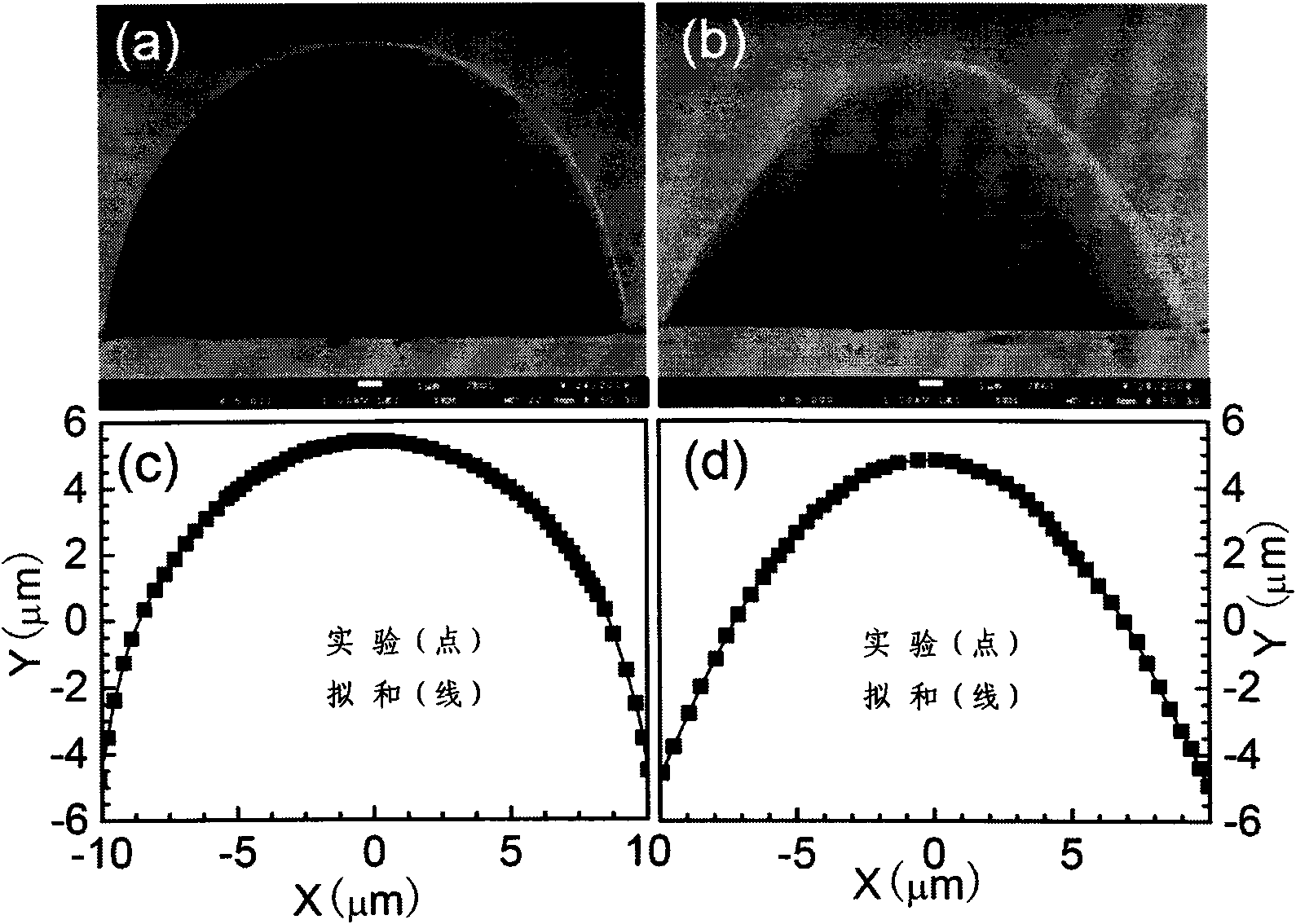
[0053] Compile the microlens program of the ellipsoid, the base radius r of the ellipsoid is 10 μm, and the height H is 10.5 μm. First use the formula x 2 +y 2 +[0.95z+(r 2 +H 2 / 2H)-H] 2 =(r 2 +H 2 / 2H) 2 Obtain the microlens model shape (0<x, y≤r, 0<z≤H) of the ellipsoid defect. Then the model is sliced horizontally (the slice thickness is 100nm). Each slice is composed of several circles with the same center and different radii (radius interval is 100nm). is 100nm), each tangent point in each slice is written into the point cloud data, and then the point cloud data of the ellipsoidal microlens model is obtained.
[0054] Create a microlens program with a parabolic sectional profile in the vertical direction. The radius r of the bottom surface of the microlens is 10 μm, and the height H is 10 μm. First use the formula z=-a(x 2 +y 2 )+H[a=0.0...
Embodiment 2
[0113] (1) Use the Visual C++ programming language to compile the point cloud data of the hexagonal aspheric microlens array model with a side length of 5 μm and different heights.
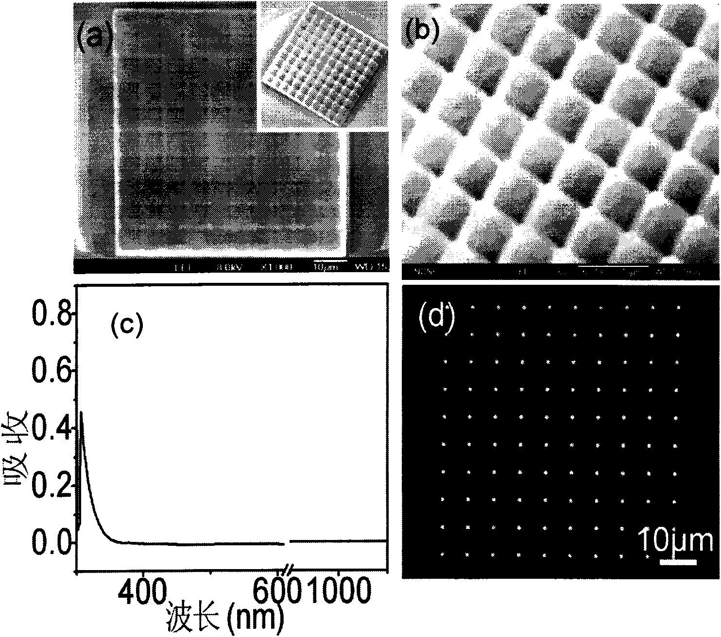
[0114] First use the formula z=-a(x 2 +y 2)+H[0<x, y≤5H is the height, a=H / 25] to obtain the shape of the aspheric microlens model, and then slice the model in the horizontal direction (slicing interval 100nm). Each slice is composed of several rings with the same center and different radii (radius interval 100nm), and each ring is composed of several tangent points (interval 100nm). For each tangent point in each slice, it is judged whether it is within the following In the equilateral hexagonal area with the center of the microlens as the center and the side length of the slice plane is 5 μm, if the point is in the hexagonal area, the point cloud data will be written, and if the point is not in the hexagonal area, it will not be written. The point cloud data of a hexagonal aspheric microlens m...
PUM
| Property | Measurement | Unit |
|---|---|---|
| length | aaaaa | aaaaa |
| length | aaaaa | aaaaa |
| wavelength | aaaaa | aaaaa |
Abstract
Description
Claims
Application Information
 - R&D
- Intellectual Property
- Life Sciences
- Materials
- Tech Scout
- Unparalleled Data Quality
- Higher Quality Content
- 60% Fewer Hallucinations
Browse by: Latest US Patents, China's latest patents, Technical Efficacy Thesaurus, Application Domain, Technology Topic, Popular Technical Reports.
© 2025 PatSnap. All rights reserved.Legal|Privacy policy|Modern Slavery Act Transparency Statement|Sitemap|About US| Contact US: help@patsnap.com


