
Optical channel performance monitoring module

A monitoring module and optical channel technology, applied in transmission monitoring/testing/fault measurement systems, electromagnetic wave transmission systems, electrical components, etc., can solve the problem that tunable filters are difficult to achieve OPM bandwidth and rate other indicators, and system signal real-time monitoring Difficulty, unable to sample signal components at the same time, etc., to achieve the effects of no diffraction effect, high-precision positioning, and fast tuning speed

Inactive Publication Date: 2009-10-07
SHANGHAI BRANCH FUZHOU GAOYI COMM CO LTD
View PDF0 Cites 5 Cited by
  • Summary
  • Abstract
  • Description
  • Claims
  • Application Information

AI Technical Summary

Problems solved by technology

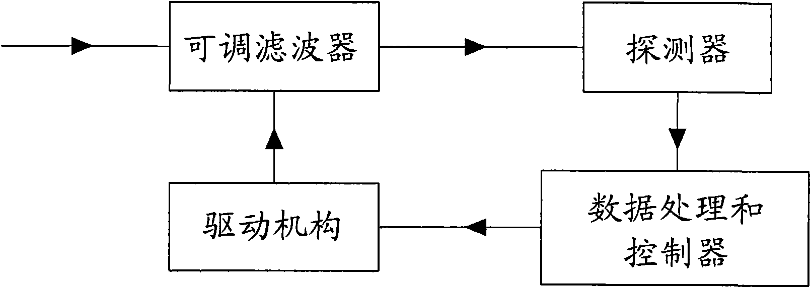
The disadvantage of interferometric OPM is that its core component, the tunable filter, is still difficult to achieve the bandwidth, rate and other indicators required by OPM.
Due to the serial scanning method, all signal components cannot be sampled at the same time, and the scanning speed is slow (generally requires several hundred ms), which makes it difficult to monitor the system signal in real time

Method used


Image

  • Optical channel performance monitoring module
  • Optical channel performance monitoring module
  • Optical channel performance monitoring module

Examples


Embodiment Construction

[0030] The present invention is described further below by specific embodiment:

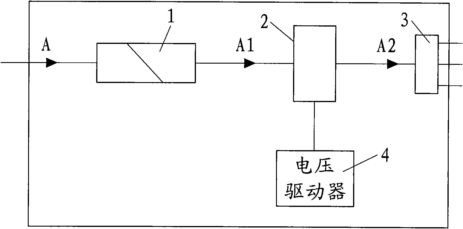
[0031] refer to image 3 , the basic unit of the present invention is as image 3 shown. The basic unit of the invention includes a collimator (1), an adjustable F-P filter (2), a photodetector (3), and a voltage driver (4). A collimator (1), a tunable F-P filter (2), and a photodetector (3) are sequentially arranged along the direction of the optical path of the monitoring input signal, and the tunable F-P filter (2) is connected to a voltage driver (4). refer to Figure 4 , wherein the tunable F-P filter (2) is composed of an electro-optic ceramic sheet (21) and reflection film layers (22), (23).

[0032] The input signal light A to be monitored is output as A1 from the collimator (1), and A1 is incident on the electro-optic ceramic sheet (21), and the front and rear surfaces of the electro-optic ceramic sheet (21) are coated with reflective films (22), (23) respectively. ), reflecting fil...


PUM


Abstract

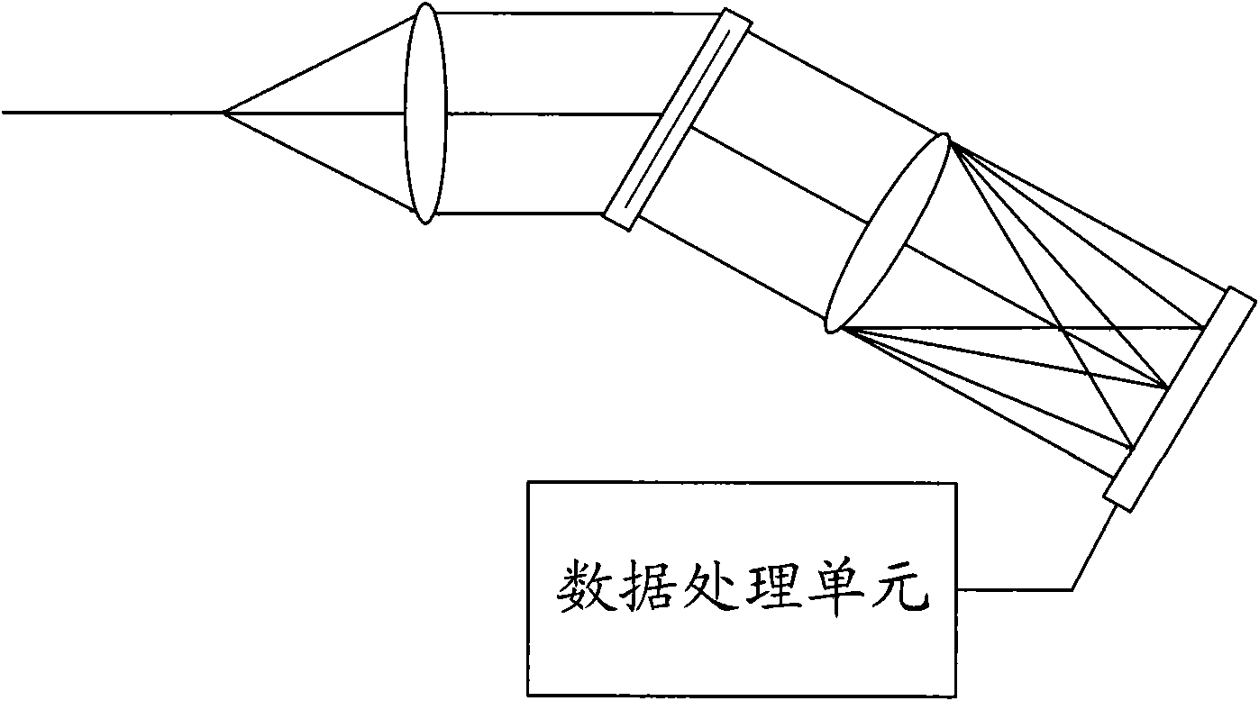
The invention belongs to the field of optoelectronic device manufacture, in particular to an optical channel performance monitoring module (OPM) which comprises basal units such as a collimator, an electrooptical ceramic wafer, an electrooptical probe, a voltage driver, and the like. Both sides of the electrooptical ceramic wafer are respectively plated by reflecting films to form an F-P filter, and the tunability of the F-P filter is realized by changing the refractive index of electrooptical ceramic. The refractive index of the electrooptical ceramic can be changed through changing an electric field on the electrooptical ceramic so that the transmissive wavelength of the F-P filter moves to scan the wavelengths and the power of various optical channels in the whole communication bandwidth and obtain the optical signal-to-noise ratios (OSNR) of the channels by certain algorithms and treatments. Due to the adoption of the rapidly responded electrooptical ceramic, the scanning time of the OPM reaches a sub-millisecond level, the defects of the prior OPMs of diffraction type and interference type are overcome, and the invention has the advantages of high response speed and stability, small size, simple structure, no diffraction influence and no mechanical control.

Description

【Technical field】 [0001] The invention belongs to the field of optoelectronic equipment manufacturing, and relates to an optical channel performance monitoring (OPM, optical performance monitoring) module used in an optical transmission system such as a dense wavelength division multiplexing (DWDM, dense wavelength division multiplexing) system. 【Background technique】 [0002] In a multi-channel optical network, the channel wavelength and power stability are very important. The stability of an optical channel depends largely on the performance of the optical transmitters in the network. As the laser ages and its operating temperature changes, both the wavelength and intensity of the laser light emitted by the laser are prone to change. In the DWDM network, due to the increase of optical channels and the narrowing of channel intervals, wavelength drift will cause crosstalk between adjacent channels, making optical channel wavelength drift and intensity jitter more obvious, w...

Claims


Application Information

Patent Timeline
Patent Type & Authority Applications(China)
IPC IPC(8): H04B10/08H04J14/02H04B10/07
Inventor 莫霜潘忠灵蒋友山
Owner SHANGHAI BRANCH FUZHOU GAOYI COMM CO LTD
Learn More