Driving circuit of liquid crystal display

A driving circuit and driver technology, applied in the direction of logic circuits using specific components, logic circuits with logic functions, static indicators, etc., can solve the problems of prolonging the discharge time of the gate line, the discharge of the gate line, and the slow characteristic deterioration.

Active Publication Date: 2009-10-28
LG DISPLAY CO LTD
View PDF0 Cites 19 Cited by
  • Summary
  • Abstract
  • Description
  • Claims
  • Application Information

AI Technical Summary

Problems solved by technology

[0019] Therefore, in the related art LCD, when the gate driving unit outputs the gate signal to each gate line of the liquid crystal panel, during a short period of time, a high-level gate voltage is supplied to the charge transistor, and thus the characteristics deteriorate relatively slowly. conduct
Meanwhile, the discharge transistor of each gate drive unit receives a high-level gate voltage for a longer period of time than the charging time of the charge transistor, so characteristic degradation proceeds much faster
This causes a problem that the discharge time of the gate line is prolonged, so that the interval to be kept in the OFF state is not cut off and an abnormal voltage is output
[0020] In addition, the charging transistor T U and discharge transistor T D are realized by a-Si:H, resulting in a charging transistor T PU and discharge transistor T PD Has the disadvantage of low mobility
Therefore, the related art LCD has a problem that the gate line is not discharged within the row time

Method used


Image

  • Driving circuit of liquid crystal display
  • Driving circuit of liquid crystal display
  • Driving circuit of liquid crystal display

Examples


Embodiment Construction

[0044] Exemplary embodiments of the present invention will now be described in detail with reference to the accompanying drawings.

[0045] First, refer to Figure 6 to Figure 13 A driving circuit for a liquid crystal display (LCD) according to a first embodiment of the present invention will be described.

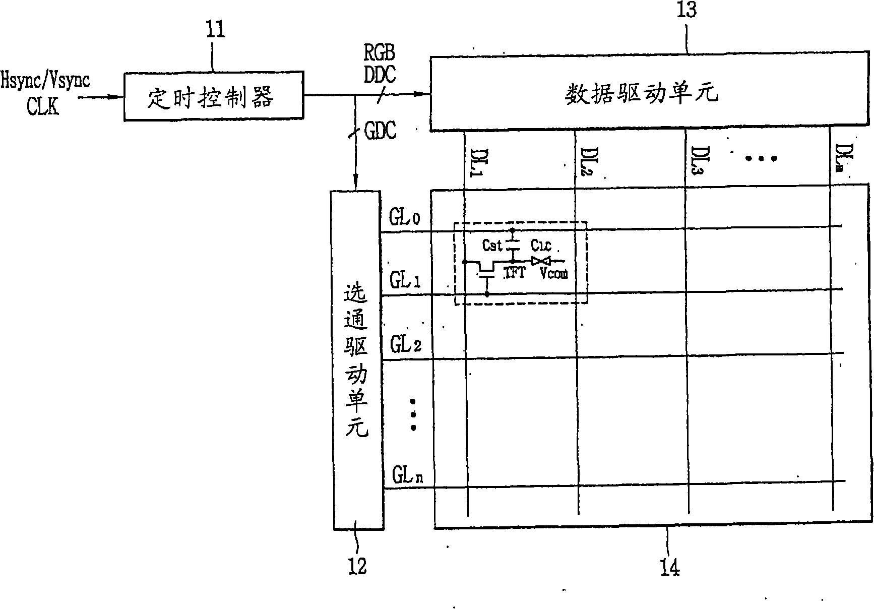
[0046] Figure 6 is a block diagram of the driving circuit of the LCD according to the first embodiment of the present invention. refer to Figure 6 , the driving circuit of the LCD according to the first embodiment of the present invention includes: a timing controller 91, which is used to output a gate control signal GDC and a data control signal DDC for controlling the drive of the gate drive unit 92 and the data drive unit 93, Sampling, rearranging and outputting the digital video data RGB; a pair of gate drive units 91 and 92, responding to the gate control signal GDC to alternately provide gate signals to the gate lines GL0-GLn of the liquid crystal panel 94; the ...


PUM


Abstract

A driving circuit of a liquid crystal display includes: a timing controller to output a gate control signal and a data control signal to control driving of a gate driving unit and a data driving unit and to output digital video data; a pair of gate driving units to be alternately driven by using at least one frame as a period to supply gate signals to gate lines of a liquid crystal panel in-response to the gate control signal; and a data driving unit to supply pixel signals to data lines of the liquid crystal panel in response to the data control signal. Degradation of characteristics of transistors constituting each gate driver can be prevented.

Description

technical field [0001] The present invention relates to a technique for driving a liquid crystal panel of a liquid crystal display (LCD), and more particularly, to an LCD drive circuit capable of avoiding deterioration of characteristics of transistors constituting a gate drive unit and elements of the gate drive unit. Background technique [0002] Recently, with the continuous progress of information technology (IT), the importance of flat panel display devices as a visual information transmission medium has been further strengthened, and in order to gain a competitive advantage in the future, flat panel display devices are required to have low power consumption, thinner and lighter and With high image quality. A liquid crystal display (LCD), a typical display device of a flat panel display device, displays images by using optical anisotropy of liquid crystals. Taking advantage of being thinner and smaller, having low power consumption and high image quality, LCDs are wide...

Claims


Application Information

Patent Timeline
Patent Type & Authority Applications(China)
IPC IPC(8): G09G3/36H03K19/173H03K19/20H03K3/3562
CPCG02F1/133G09G3/3648G09G2300/04
Inventor 金珍浩慎弘縡
Owner LG DISPLAY CO LTD
Why Eureka
Try Eureka