
Control method of IPM electromotor for driving electric motor car

An electric vehicle and algorithm technology, applied in the direction of single motor speed/torque control, electronic commutator, etc., can solve the problems of actual capacity limitation, affecting overall performance, and large battery voltage variation range, so as to achieve less system expenditure and rely on small effect

Inactive Publication Date: 2009-10-28
マイウェイ技研
View PDF0 Cites 47 Cited by
  • Summary
  • Abstract
  • Description
  • Claims
  • Application Information

AI Technical Summary

Problems solved by technology

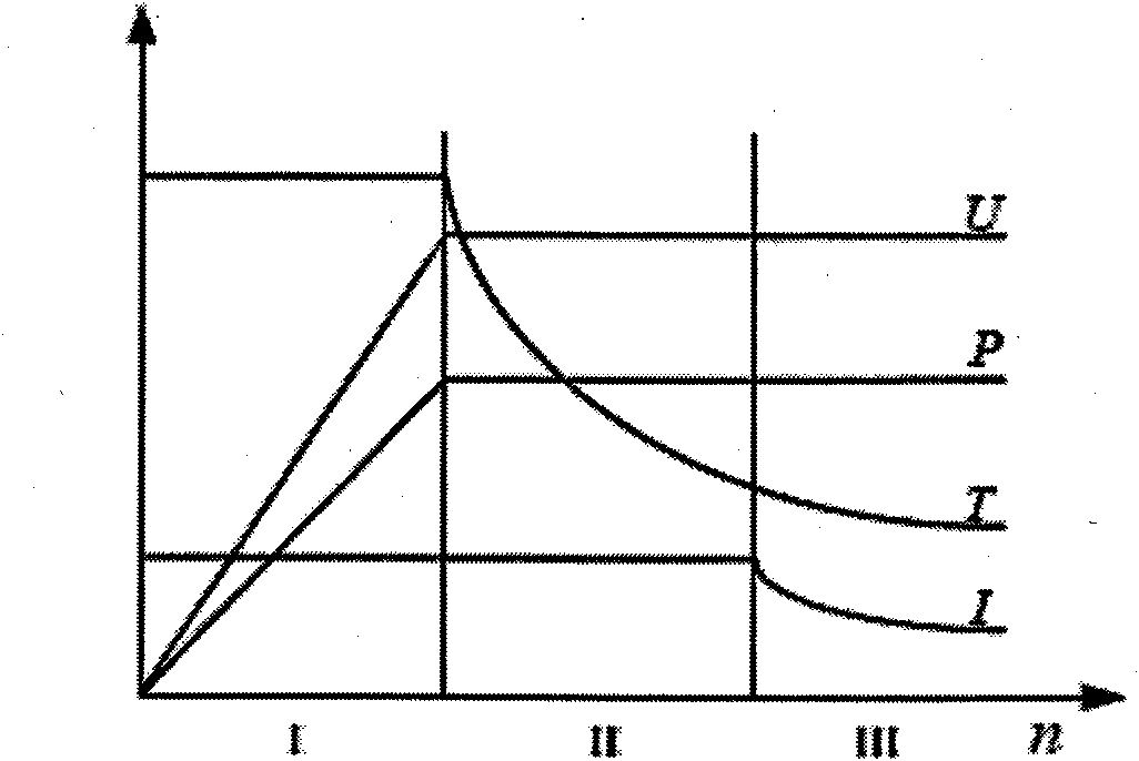
[0003] Electric vehicles need to operate in a wide range of loads and speeds, as well as under complex road conditions. The operating conditions of the driving motors are very harsh, not only in the road surface, climate and greatly changing traffic conditions, but more importantly, due to the Motors for automobiles are powered by limited energy sources such as batteries, and the voltage of batteries varies in a large range, especially when the voltage drops to a critical value, the actual capacity is greatly limited. performance

Method used

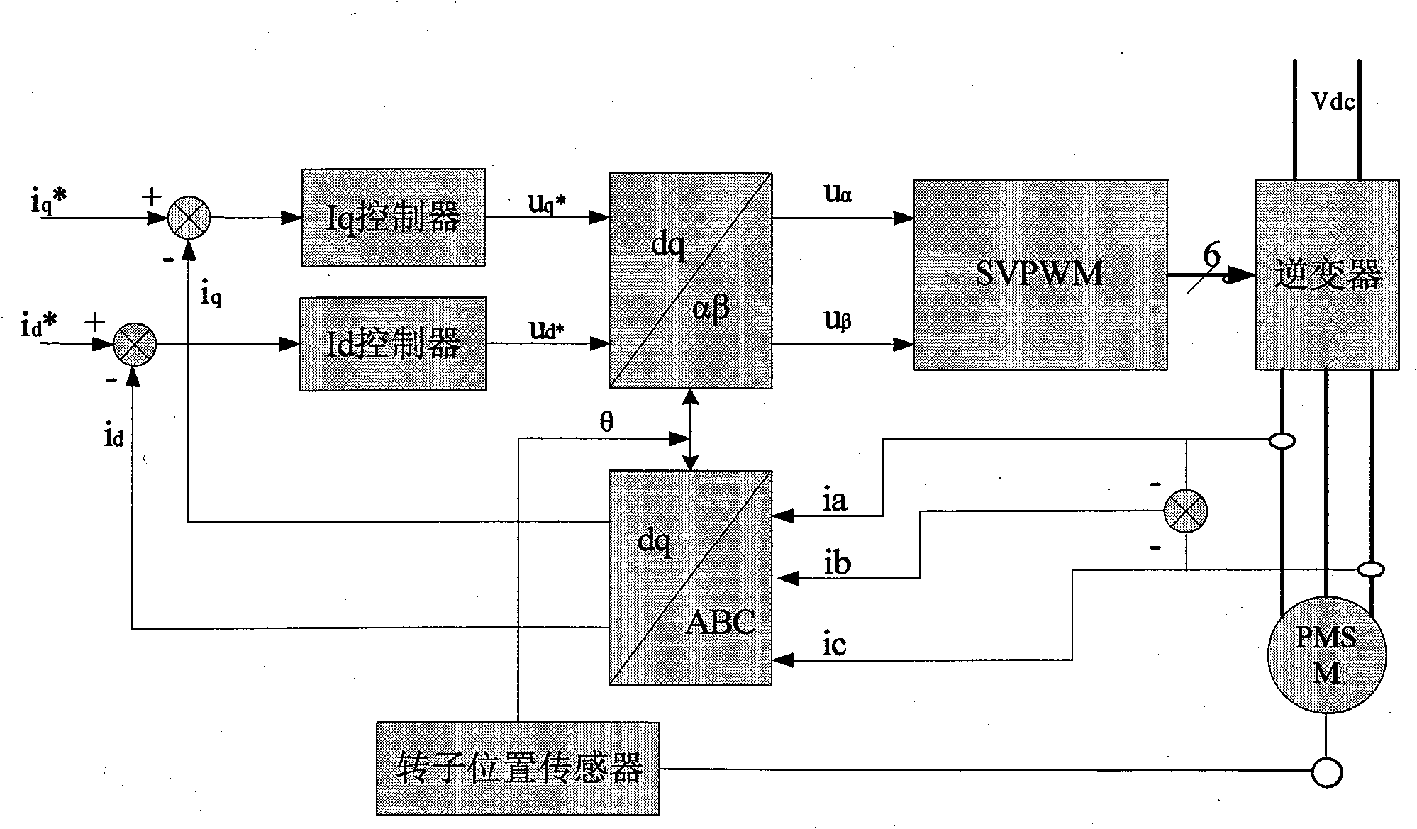

Image

  • Control method of IPM electromotor for driving electric motor car
  • Control method of IPM electromotor for driving electric motor car
  • Control method of IPM electromotor for driving electric motor car

Examples


Embodiment Construction

[0018] The present invention will be described in further detail below in conjunction with the accompanying drawings.

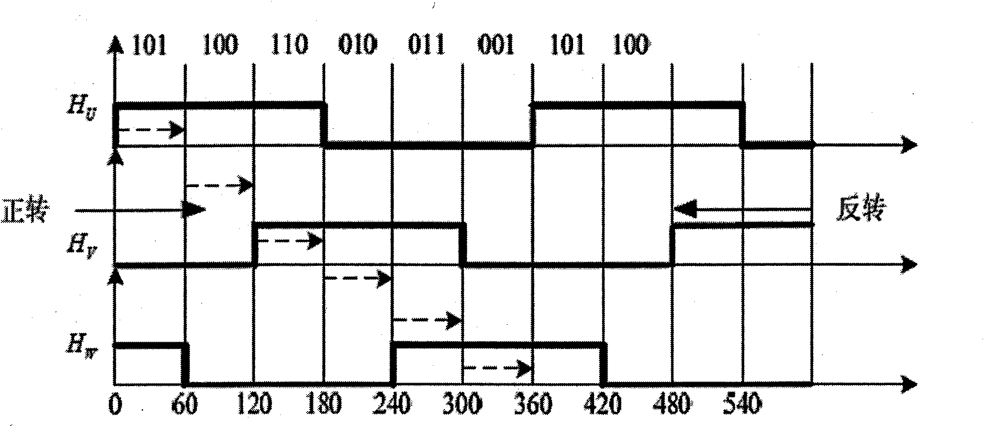
[0019] 1) The detection of the motor rotor position in this motor drive control system is realized by a low-cost Hall position sensor. The Hall position sensor consists of three Hall position sensors fixed on the motor housing and a steel tooth fixed on the rotor The tooth groove made of soft magnetic material is installed coaxially with the rotor through the steel disk. When the tooth on the steel disk enters the detection point of the Hall sensor, the detection element outputs a high level. When the tooth on the steel disk enters the detection point of the Hall sensor When the point is detected, the output is low. Three Hall position sensors, which are installed in space with a difference of 120° in electrical angle. When the motor runs continuously, there will be a transition edge of the Hall position signal every 60 electrical degrees. Therefore, 6 defi...


PUM


Abstract

The invention discloses a control method of an IPM electromotor for driving an electric motor car. According to the working characteristics of the IPM electromotor used on the electric motor car and the characteristics and advantages of various control methods, a segmental control strategy and a method for accurately detecting the start of the electromotor as well as the position and the rotational speed of a rotator during the operation provided are provided. A hall sensor is used for carrying out the method of rough positioning first and scanning next, so that the relatively accurately positioning of the initial position of the rotation in a static state can be realized, the electromotor can be successfully and easily started no matter in the case of idle load, light load or heavy load,and the reliability of the start and operation of the electromotor can be greatly improved. After the IPM electromotor is successfully started, output signals of the hall position sensor undergo rising edge capturing and trailing edge capturing by using software. According to a signal jumping edge, the position of the rotator is corrected in the cases of a low rotational speed and a high rotational speed. When the electromotor operates, a T method is adopted for speed measurement, and an algorithm undergoes certain adjustment in the cases of the low rotational speed and the high rotational speed. When the position and the rotational speed of the rotator during the operation are correctly detected, the segmental control strategy such as peak torque current control and field-weakening control can be adopted so as to ensure that a peak torque is output during the operation of the electromotor.

Description

1. Technical field [0001] The invention mainly relates to a drive control method for an IPM permanent magnet synchronous motor used in an electric vehicle. The motor is controlled with high torque output, wide-range speed regulation and high-efficiency operation as the ultimate goals. 2. Background technology [0002] The development of electric vehicles is an effective way to solve the oil resource crisis and the increasingly serious environmental pollution problems. Compared with internal combustion engine vehicles, electric vehicles have significant advantages such as significantly reducing urban air and noise pollution, and more reasonable and extensive energy utilization. Among them, the electric drive system is the heart of electric vehicles, and it is the fundamental guarantee for improving the driving performance, mileage and reliability of electric vehicles. Especially under the background that the current battery technology has not made a breakthrough, an excellen...

Claims


Application Information

Patent Timeline
IPC IPC(8): H02P6/08H02P6/16
Inventor 贾要勤杨容杨仲庆
Owner マイウェイ技研
Learn More