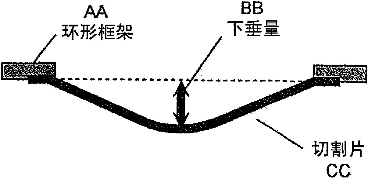
Laser dicing sheet and method for manufacturing chip body
A technology of laser cutting and matrix, which is applied in the direction of film/sheet adhesive, semiconductor/solid device manufacturing, manufacturing tools, etc. It can solve the problems that the cutting sheet cannot be realized, and there is no use of laser cutting sheet, so as to improve the shape restorative effect
- Summary
- Abstract
- Description
- Claims
- Application Information
AI Technical Summary
Problems solved by technology
Method used
Image
Examples
Embodiment 1
[0160] Prepare 2-hydroxyethyl acrylate (2HEA), 4,4'-dicyclohexylmethane isocyanate (H 12 MDI) and polyester polyol (Polyol: molecular weight 826) represented by the following formula, molar ratio 2HEA:H 12 MDI:Polyol=2:4:3. H 12 MDI is reacted with polyester polyol, and 2HEA is added to the resulting reaction product to obtain a urethane acrylate oligomer.
[0161] (chemical 1)
[0162]
[0163] [0086] Next, 50 parts by weight of urethane acrylate oligomer, 50 parts by weight of energy ray curable monomer (isobornyl acrylate), and 3 parts by weight of photoinitiator (Chiba Specialty Chemicals) Co., Ltd. 184) was mixed to obtain a coating liquid for coating film formation.
[0164] [0087] By means of a spray die (fountain die) method, the above-mentioned coating solution is coated with a thickness of 100 μm on a polyethylene terephthalate (PET) film (manufactured by Lintec Co., Ltd.) that has undergone a silicone release treatment. On SP-PET3801), a resin composition la...
Embodiment 2
[0170] Prepare 2-hydroxyethyl acrylate (2HEA), isophorone diisocyanate (IPDI) and polytetramethylene glycol (PTMG: weight average molecular weight 2000), molar ratio 2HEA:IPDI:PTMG=2:5: 4. Initially, IPDI and PTMG were reacted, and 2HEA was added to the resulting reaction product to obtain a urethane acrylate oligomer.
[0171] [0093] Next, 50 parts by weight of urethane acrylate oligomer, 50 parts by weight of energy ray curable monomer (isobornyl acrylate), 0.5 part by weight of photoinitiator (Chiba Specialty Chemical Co., Ltd. Dalokyua 1173) manufactured in 2010 was mixed to obtain a coating liquid for coating film formation.
[0172] [0094] Thereafter, a substrate film was produced in the same manner as in Example 1 using the obtained coating solution, and an adhesive layer was provided in the same manner to obtain a laser-cut sheet. The results are shown in Table 1.
Embodiment 3
[0174] Prepare 2-hydroxyethyl acrylate (2HEA), isophorone diisocyanate (IPDI) and polypropylene glycol (PPG: weight average molecular weight 2000), with a molar ratio of 2HEA:IPDI:PPG=2:5:4. First, IPDI and PPG were reacted, 2HEA was added to the resulting reaction product, and a urethane acrylate oligomer was obtained.
[0175] [0096] Next, 50 parts by weight of urethane acrylate oligomer, 50 parts by weight of energy ray curable monomer (isobornyl acrylate), 0.5 part by weight of photoinitiator (Chiba Specialty Chemical Co., Ltd. Darokiyua 1173) produced in 2010 was mixed to obtain a coating solution for coating film formation.
[0176] [0097] Afterwards, a substrate film was produced in the same manner as in Example 1 using the obtained coating solution, and an adhesive layer was similarly provided to obtain a laser-cut sheet. The results are shown in Table 1.
PUM
| Property | Measurement | Unit |
|---|---|---|
| thickness | aaaaa | aaaaa |
| thickness | aaaaa | aaaaa |
Abstract
Description
Claims
Application Information
 - R&D
- Intellectual Property
- Life Sciences
- Materials
- Tech Scout
- Unparalleled Data Quality
- Higher Quality Content
- 60% Fewer Hallucinations
Browse by: Latest US Patents, China's latest patents, Technical Efficacy Thesaurus, Application Domain, Technology Topic, Popular Technical Reports.
© 2025 PatSnap. All rights reserved.Legal|Privacy policy|Modern Slavery Act Transparency Statement|Sitemap|About US| Contact US: help@patsnap.com


