Biomass direct thermal cracking generator and cracking method thereof

A thermal cracking and generator technology, used in chemical instruments and methods, biofuels, indirect heating and dry distillation, etc., can solve the problems of low thermal efficiency, high energy consumption cost, high transportation power, etc., to increase the heating contact area, overcome the Thermal inefficiency, the effect of reducing operating costs

Inactive Publication Date: 2013-02-20
北京联合创业环保工程股份有限公司
View PDF4 Cites 0 Cited by
  • Summary
  • Abstract
  • Description
  • Claims
  • Application Information

AI Technical Summary

Problems solved by technology

[0004] In this tar cracking method, coal and biomass fuel heating technology and electric heating technology generally use indirect heating, its thermal efficiency is relatively low, and its energy consumption cost is relatively high, and the waste heat generated by it is not universally utilized. and promotional value
The high temperature pyrolysis gas of biomass will have some heat loss in the process of being transported to the cracking equipment
In addition, when burning coal and biomass fuel, it is necessary to configure a complex structure including a large-volume combustion chamber, and requires high transportation force, so the manufacturing cost and operating cost of the biomass pyrolysis generator are relatively high

Method used


Image

  • Biomass direct thermal cracking generator and cracking method thereof

Examples


Embodiment Construction

[0017] The present invention and the operation mode of the equipment will be described in detail below in conjunction with the accompanying drawings and embodiments.

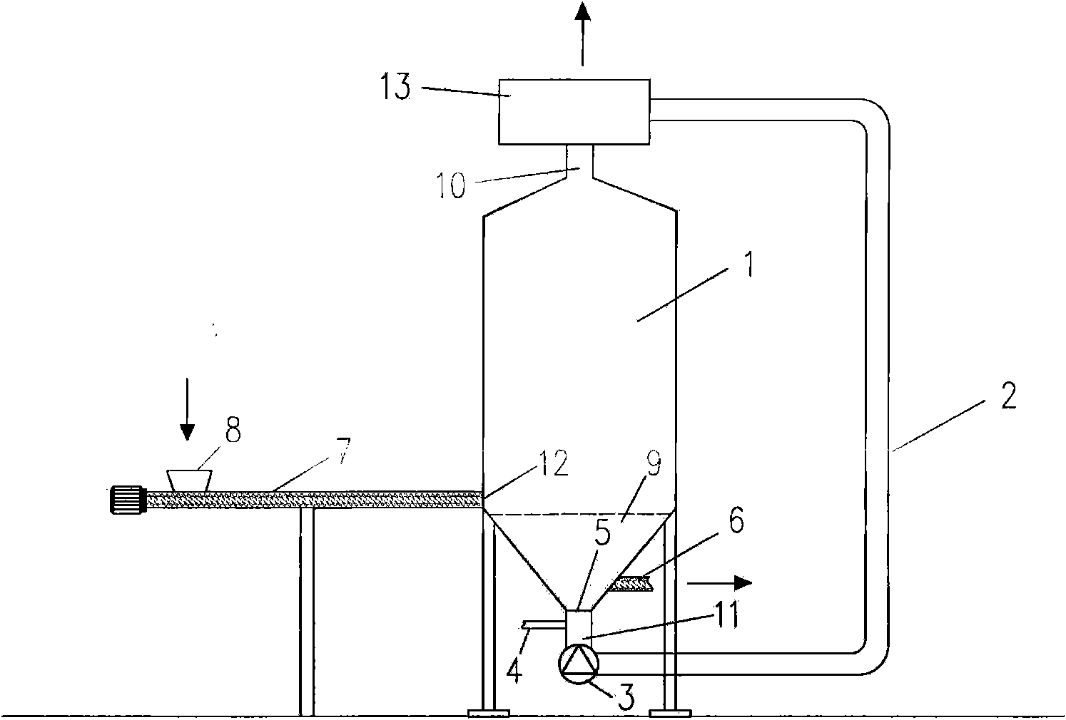
[0018] Such as figure 1 Shown is a schematic structural diagram of the biomass direct pyrolysis generator used in the present invention. The generator comprises: a thermal cracking reaction chamber 1, a gas delivery pump 3 arranged at its lower part, a gas return burning pipe 2 connected to the gas outlet 10 side on the upper part of the thermal cracking reaction chamber 1, and the gas burning back pipe 2 passes through The fuel gas delivery pump 3 is connected to the combustion heating chamber 9 positioned below the thermal cracking reaction chamber 1, the thermal cracking reaction chamber 1 and the combustion heating chamber 9 are divided due to different functions, and there is no actual partition between them to separate, from The burn-back gas input from the gas burn-back pipe 2 and the oxygen input throug...


PUM

PropertyMeasurementUnit
diameteraaaaaaaaaa

Abstract

The invention provides a biomass direct thermal cracking generator and a cracking method thereof. The generator comprises a thermal cracking reaction chamber used for carrying out thermal cracking reaction, and a combustion heating chamber is arranged below the thermal cracking reaction chamber; the generator also comprises a fuel gas conveying pump arranged below the combustion heating chamber, a fuel gas burn-back tube communicated with a fuel gas outlet which is positioned at the upper part of the thermal cracking reaction chamber and an air distribution and an ignition unit ; wherein, the fuel gas burn-back tube is connected to the combustion heating chamber by the fuel gas conveying pump; the air distribution and an ignition unit are communicated with the combustion heating chamber. In the invention, combustible gas generated in the cracking reaction is directly used as the heating source for biomass thermal cracking to heat the biomass in the premise of not igniting thermal decomposition materials in the generator, thus improving thermal efficiency while increasing heating contact area of materials in the thermal cracking generator, fully mixing and thermally decomposing the materials, greatly improving reaction efficiency and improving fuel gas quality while reducing pollution of hazardous gases such as CO2 and smoke dust.

Description

technical field [0001] The invention relates to a biomass pyrolysis method and equipment thereof, in particular to a biomass direct pyrolysis generator and a pyrolysis method thereof. Background technique [0002] There are two main conventional biomass gasification methods at home and abroad, one is the oxidation method, which is divided into fixed bed gasification, fluidized bed gasification and entrained bed gasification, most of which use air as the gasification agent, and tar cannot The good ones are separated and utilized. Another method adopts the anaerobic pyrolysis dry distillation process, and the biomass tar can be separated well, but it cannot be directly used as a heat source, and the gas production of this process is low. After learning from the production experience of coal tar cracking, biomass tar can also be cracked at present. The process is: the gas produced by anaerobic thermal cracking carries tar together into the cracking furnace for catalytic cracki...

Claims


Application Information

Patent Timeline
Patent Type & Authority Patents(China)
IPC IPC(8): C10B53/02C10B47/00B01J23/02B01J21/10
CPCY02E50/14Y02E50/10
Inventor 赵洪叶魏晓明徐冬利
Owner 北京联合创业环保工程股份有限公司
Why Eureka
Try Eureka