Cooling cylinder compression cycle of rotor-type compressor

A compressor and rotor type technology, applied in the field of circulation system, can solve the problems of increasing condensing load, increasing condensing load, cycle deterioration, etc., and achieve the effects of reducing motion resistance, reducing net compression work, and improving oil circuit

Inactive Publication Date: 2013-07-17
童夏民
View PDF5 Cites 0 Cited by
  • Summary
  • Abstract
  • Description
  • Claims
  • Application Information

AI Technical Summary

Problems solved by technology

[0002] The current hermetic compressor, whose guiding theory is the reverse Carnot cycle, isentropic adiabatic compression is considered to be the highest compression efficiency, so the vapor compression process is close to adiabatic compression, and the exhaust temperature can reach 150°C, much higher than the condensation temperature T K 50~55℃, it is obvious that most of the electric energy is converted into exhaust superheating and wasted, and increases the condensation load; while the evaporation pressure P required by the cycle O ~Condensing pressure P K The pressure difference load consumes a small amount of compression net work, which can be found in the M 1 (Refer to the third last line on the next page) Use nitrogen or air to do the corresponding pressure difference experiment to verify
On the other hand, the heat released by compression and the motor accumulates on the cylinder wall, and the intake air suffers from strong thermal expansion and loses cooling capacity, which further increases the exhaust temperature and increases the condensation load, which worsens the cycle.

Method used


Image

  • Cooling cylinder compression cycle of rotor-type compressor
  • Cooling cylinder compression cycle of rotor-type compressor
  • Cooling cylinder compression cycle of rotor-type compressor

Examples


Embodiment Construction

[0035] The specific embodiments of the present invention will be further described in detail below in conjunction with the accompanying drawings.

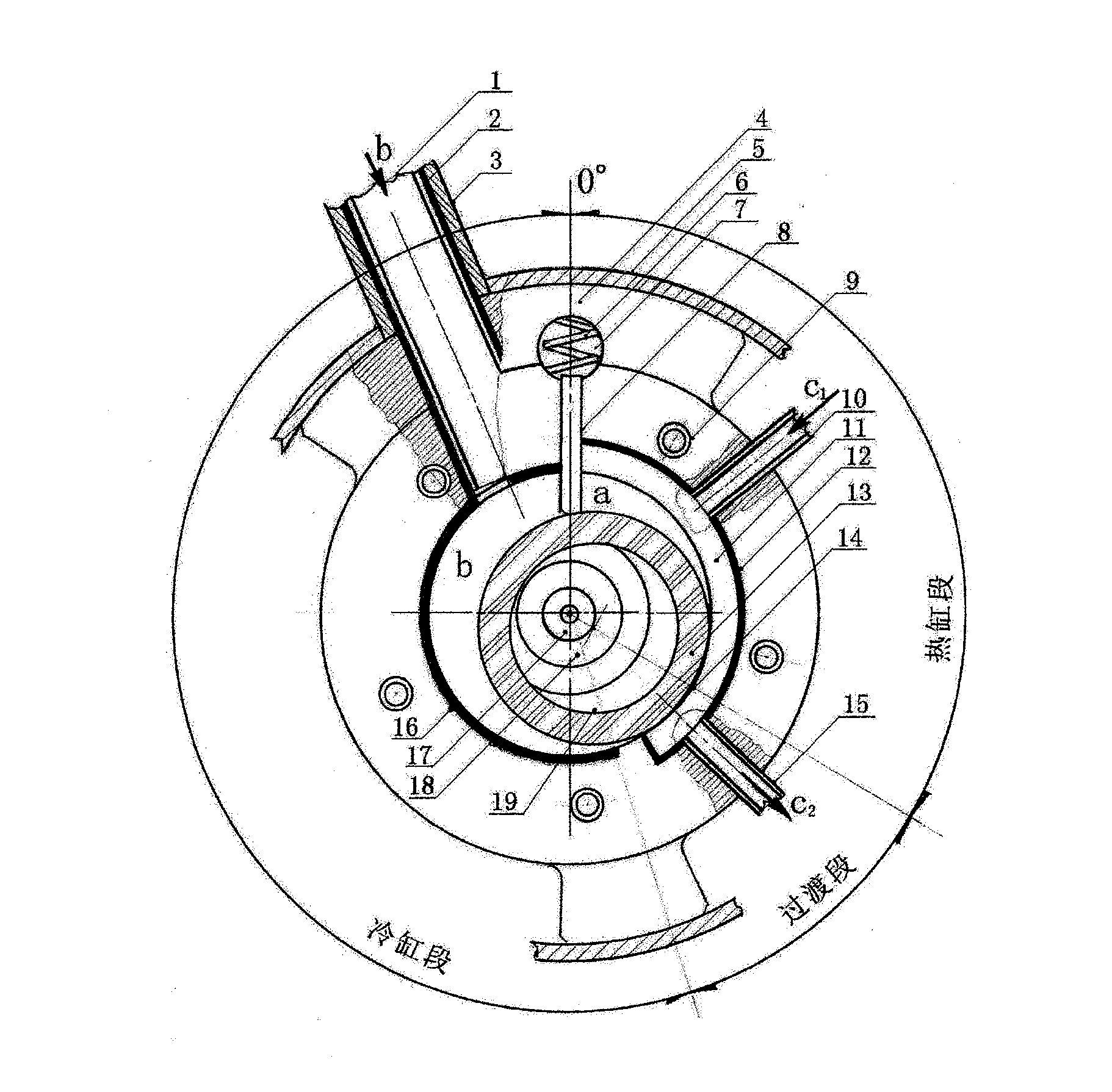
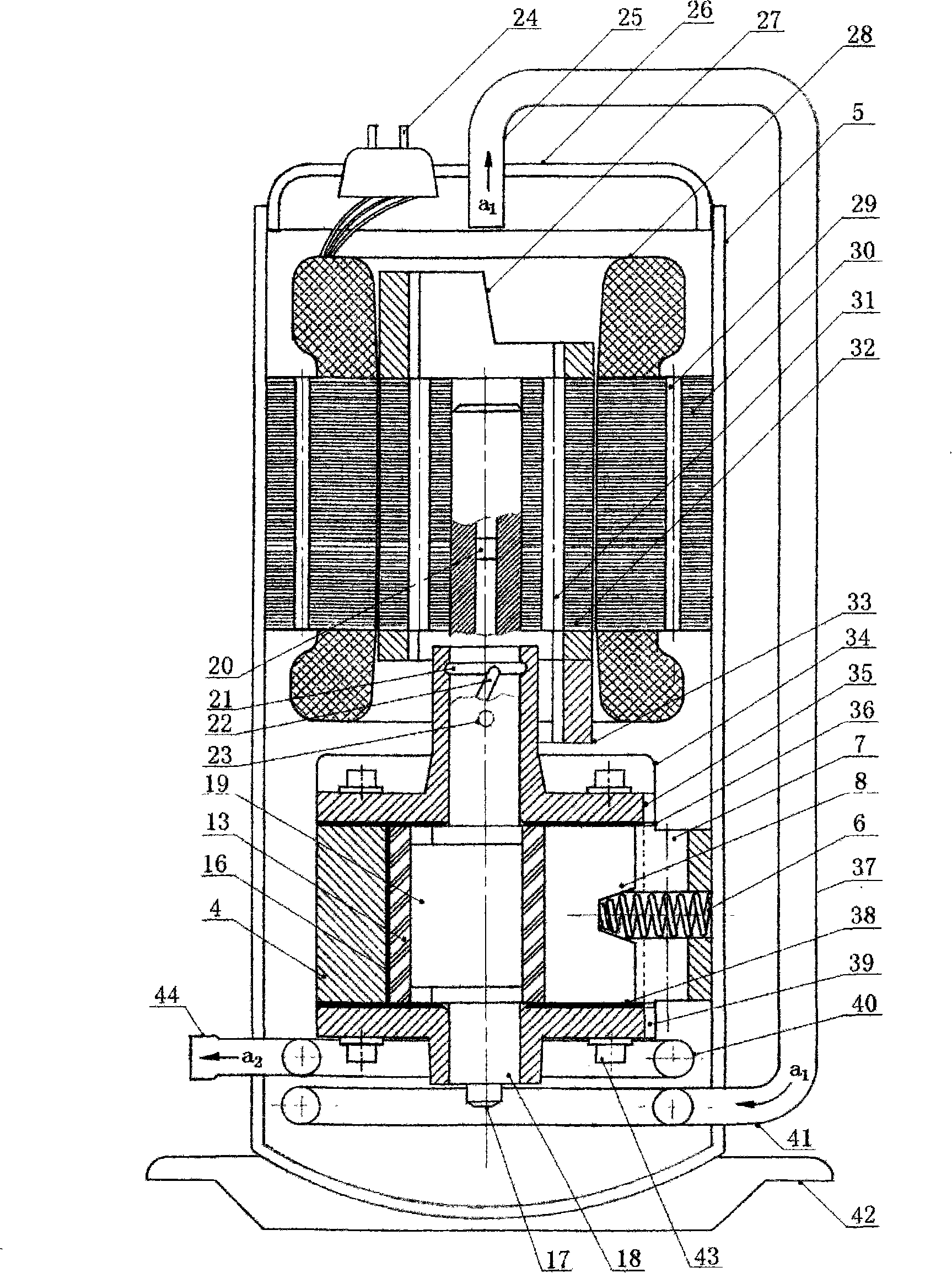
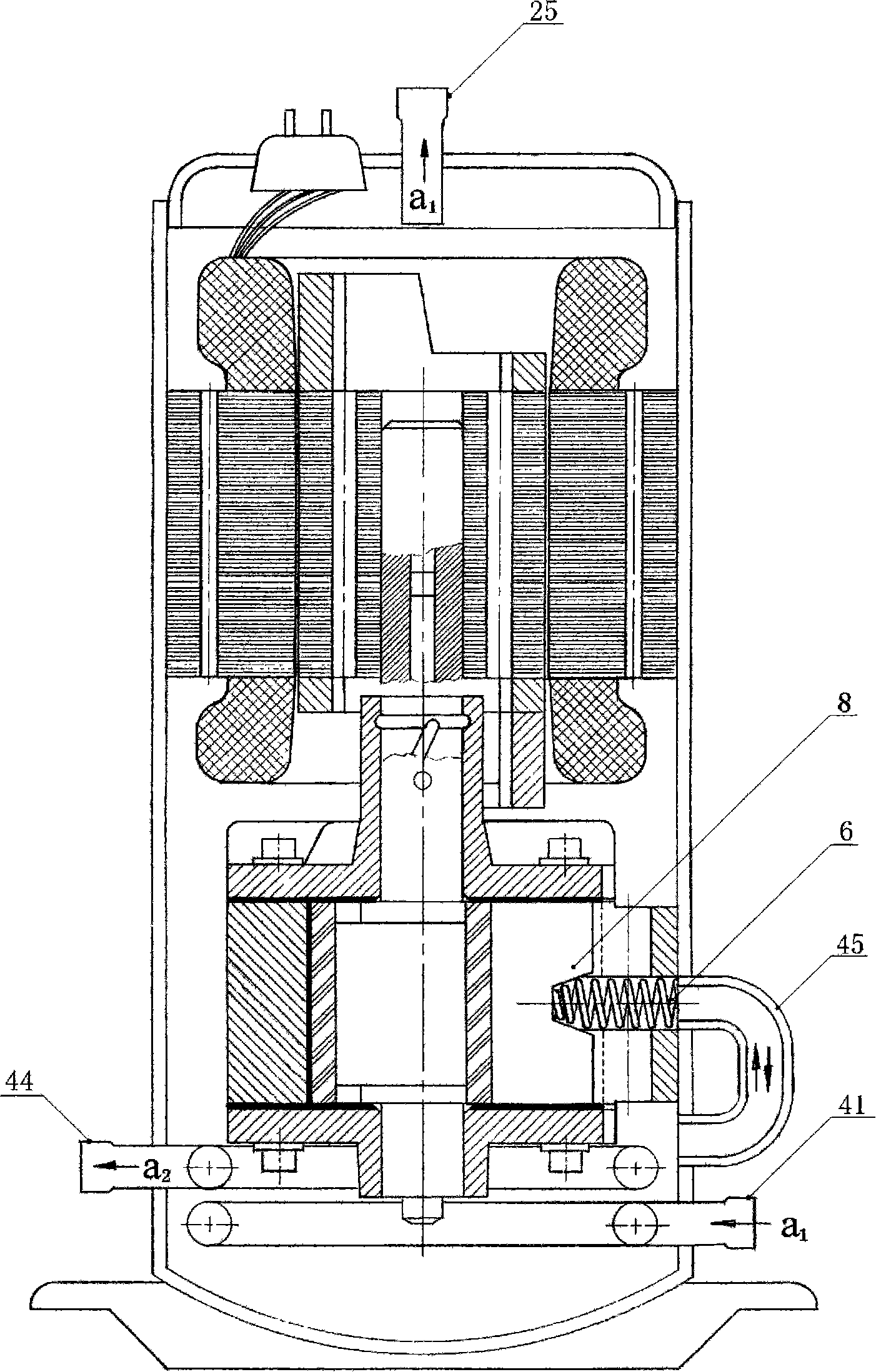
[0036] See attached figure 1 : Suction pipe 1, suction pipe insulation layer 2, suction duct 3, cylinder 4, housing 5, spring 6, tongue oil hole 7, tongue 8, screw hole 9, inlet duct 10, thermal cylinder cooling Block 11, hot cylinder insulation layer 12, rolling rotor 13, tangent point 14, outlet conduit 15, cold cylinder insulation layer 16, oil suction nozzle 17, main shaft 18, eccentric wheel 19.

[0037] The (closest point) tangent point 14 of the rolling rotor 13 and the cylinder 4 is set at the position when the exhaust valve is opened, distributed according to the compression ratio, b is the suction chamber, and a is the condensing pressure P K Isobaric compression chamber; the cylinder wall of the section a from the tangent point 14 to the tongue 8 is the condensing pressure P K The strongly exothermic section of isobar...


PUM


Abstract

The invention relates to a cycling system for improving the efficiency of a cooling compressor, cooling cylinder compression cycle for short. The cooling cylinder compression cycle of a rotor-type compressor is mainly realized in four aspects: a. cooling cylinder compression, i.e. performing low-temperature cooling to a compression strong-heat-release cylinder wall surface (defined as a heat cylinder and others are cooling cylinders), coating heat insulating ceramic on the surfaces of a tongue piece and a rolling rotor, pushing compression heat release to a cooled heat cylinder, and increasing the area of the heat cylinder or reduce the rotational speed so as to fully discharge the compression heat release and prevent the discharged gas from overheating and then to reduce the compression net work and the condensation load; b. cooling cylinder gas suction, i.e. performing the isolation of gas phase from heat insulation to high-pressure gas discharge, the cooling and heat cylinders, upper and lower covers and a gas suction pipe, and ensuring the low-temperature characteristic of a gas suction chamber by means of continuous gas suction and heat cylinder cooling so as to obtain greater cold energy; c. oil way improvement, i.e. increasing the gas-suction force; and d. recovery gas discharge overheating and motor heat releasing, for purposes of heating and compensating absorptive lubricant, wherein an absorbent has low partial pressure and strong absorption capability on the surfaces of the cooling cylinders so that the cold energy is further increased and the compression work is further reduced.

Description

technical field [0001] A circulation system of a vapor compression refrigeration compressor, in particular a circulation system of a rotary refrigeration compressor. technical background [0002] The current hermetic compressor, whose guiding theory is the reverse Carnot cycle, isentropic adiabatic compression is considered to be the highest compression efficiency, so the vapor compression process is close to adiabatic compression, and the exhaust temperature can reach 150°C, much higher than the condensation temperature T K 50~55℃, it is obvious that most of the electric energy is converted into exhaust superheating and wasted, and increases the condensation load; while the evaporation pressure P required by the cycle O ~Condensing pressure P K The pressure difference load consumes a small amount of compression net work, which can be found in the M 1 (See the penultimate line on the next page) to do the corresponding pressure difference experiment with nitrogen or air to ...

Claims


Application Information

Patent Timeline
Patent Type & Authority Patents(China)
IPC IPC(8): F04C18/332F04C29/02F04C29/04
Inventor 吉阿明童夏民
Owner 童夏民
Why Eureka
Try Eureka