Burner, burning heating method and burning heating equipment

A burner and gas technology, applied in the field of combustion heating methods, combustion heating equipment, and burners, can solve the problems of affecting work efficiency, high ineffective power consumption, low thermal efficiency, etc., so as to reduce energy consumption, avoid diffusion, and improve thermal efficiency. Effect

Inactive Publication Date: 2009-11-11
原所良
View PDF0 Cites 10 Cited by
  • Summary
  • Abstract
  • Description
  • Claims
  • Application Information

AI Technical Summary

Problems solved by technology

Because this type of burner adopts open combustion to supplement air, its common defects are: because it burns while mixing, the mixing effect of air and gas is not good, and it will start to burn when the mixing is uneven, resulting in a flame front. If the air-fuel ratio is too large, the combustion calorific value is not high, and the air-fuel ratio behind the flame front is too small, so that the combustion of the gas is incomplete; open combustion forms natural convection heat transfer with the atmosphere, and most of the heat released by combustion follows the natural The circulating cold air spreads outward, so a lot of heat energy is wasted, and the ineffective power consumption is more energy efficient
Because the forced ventilation of the fan is used for mixing, the following defects generally exist in this type of burner: 1) The air flow of the forced ventilation of the fan is relatively fast, and the gas flow follows the high-speed air flow in the burning disc of the burner, and it burns while mixing. Insufficient, resulting in insufficient combustion of gas; 2) The fan will generate forced convection heat transfer, which speeds up the heat diffusion, wastes a lot of heat energy, and has more ineffective power consumption; 3) The small fire is easily blown out by the fan when switching between large and small fires. Affect work efficiency; 4) The operation of the fan consumes electric energy, and the noise pollution of the fan operation is very serious
Therefore, there is no burner technical solution to solve the problem of low thermal efficiency in the prior art

Method used


Image

  • Burner, burning heating method and burning heating equipment
  • Burner, burning heating method and burning heating equipment
  • Burner, burning heating method and burning heating equipment

Examples


Embodiment 1

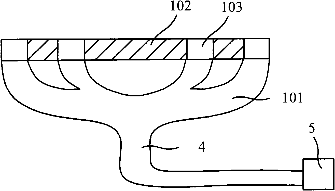
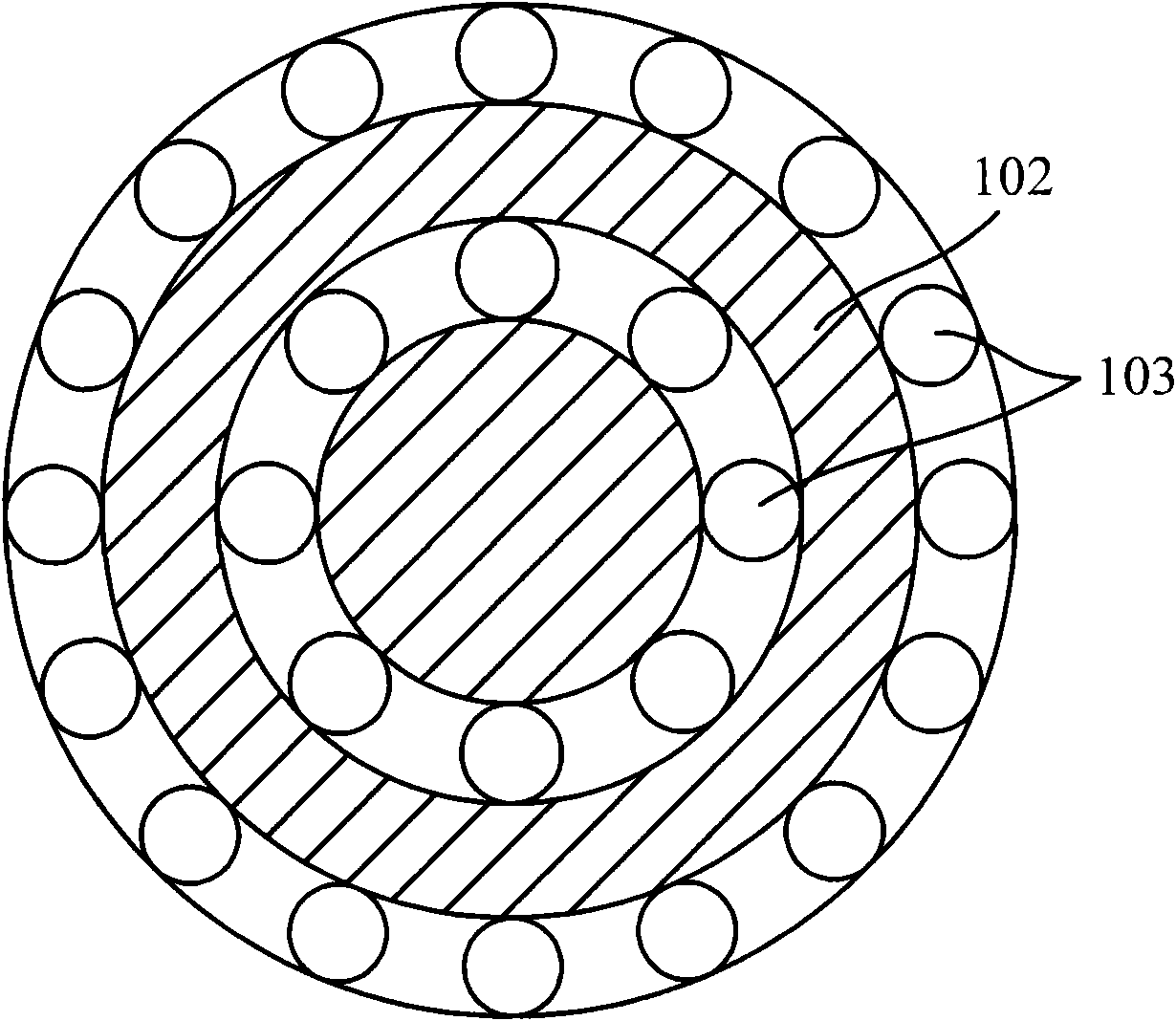
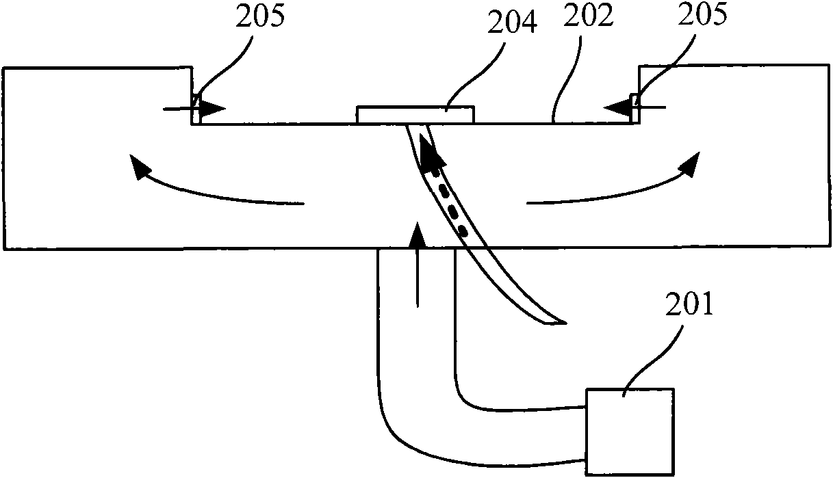
[0047] Such as image 3 Shown is a schematic structural view of the first embodiment of the burner of the present invention. The burner in this embodiment includes a distribution chamber 301 and a plurality of gas mixing pipes 302 . Wherein, the distributing chamber 301 can be formed by a disc-shaped connecting seat 303 and a disc-shaped cooktop base 304 that are relatively fastened together, so as to form a cavity 309 inside the distributing chamber 301 . A gas inlet 305 is provided on the wall of the distribution chamber 301, such as image 3 As shown, the gas inlet 305 can be set on the stove base 304 as the lower end surface of the distribution chamber 301 , and the cavity 309 in the distribution chamber 301 communicates with the gas pipeline 4 of the gas source 5 through the gas inlet 305 . A plurality of gas outlets 306 are arranged on the connection seat 303 as the upper end surface of the distribution chamber 301, and each gas outlet 306 is respectively provided with...

Embodiment 2

[0058] Such as Figure 5 Shown is the structural schematic diagram of the second embodiment of the burner of the present invention. This embodiment is based on the first embodiment, a combustion disc 311 is set in the burner, a plurality of combustion through holes 313 are opened on the combustion disc 311, and the outlet ends of each gas mixing pipe 302 are embedded and fixed on the combustion disc 311 In each of the combustion through holes 313, the combustion disc 311 is exposed through the combustion through holes 313, and is used to provide the mixed gas to burn on the combustion disc 311.

[0059] The setting of the combustion disc 311 can fix the outlet ends of the gas mixing pipes 302 and concentrate the combustion flame, which is suitable for the requirements of common combustion heating equipment. Moreover, the setting of the combustion disc 311 can relatively isolate the flame from the gas mixing tube 302, and has a protective effect on the gas mixing tube 302, red...

Embodiment 3

[0062] Such as Figure 6 Shown is a schematic structural view of the third embodiment of the burner of the present invention. On the basis of the first embodiment, the burner adds the structure of the mixing device. The burner in this embodiment is also provided with a mixing aid piece 312 in the gas mixing pipe 302 as a mixing aid device for guiding the mixed gas to form a turbulent flow. The shape of the mixing aid sheet 312 and the setting position in the gas mixing tube 302 can be in various ways. It is preferable to set the sheet-like mixing aiding chip 312 parallel to the cross section of the gas mixing tube 302, and align the outer edge contour with the gas mixing tube 302. The mixing-aiding sheet 312 whose cross-sectional inner profile is suitable is blocked in the air-mixing pipe 302, and a notch is provided on the edge of the mixing-aiding sheet 312, such as Figure 7shown. A kind of preferred arrangement mode is: the longer section in the middle part of gas mixin...


PUM


Abstract

The invention relates to a burner, a burning heating method and burning heating equipment. The burner comprises a distributor chamber and gas mixing pipes, wherein the distributor chamber is provided with a cavity, and a fuel gas inlet is arranged on the distributor chamber; the inlet ends of the gas mixing pipes are communicated with the cavity of the distributor chamber so as to obtain fuel gas; the side wall of each gas mixing pipe is provided with at least one gas inlet hole used for absorbing combustion improver to be mixed with the fuel gas; and the outlet ends of the gas mixing pipes are used for providing mixing gas of the fuel gas and the combustion improver for burning. The burning heating method comprises the steps of distributing and leading the fuel gas into more than one gas mixing pipe; leading the combustion improver into the gas mixing pipes and mixing the combustion improver and the fuel gas in the gas mixing pipes through a set process to form the mixing gas; and enabling the mixing gas to flow out of the gas mixing pipes for burning. The burning heating equipment adopts the burner of the invention. The technical scheme provided by the invention improves the mixing effect of the fuel gas and air in the mode of burning after mixing, thereby improving the thermal efficiency and reducing the energy consumption and the environmental pollution.

Description

technical field [0001] The present invention relates to a burner, a combustion heating method, and combustion heating equipment, in particular to a burner used as a combustion head for combustion heating equipment, and to a combustion heating method performed by the burner, as well as a burner using the burner A variety of combustion heating equipment such as gas stoves, boilers and water heaters. Background technique [0002] Existing various combustion heating equipment, such as Chinese cooking gas stoves, stew gas stoves, civil gas stoves, small and medium-sized gas boilers and civil gas water heaters on the market, all need to use burners to connect to the gas source for heating. Burn to heat. These burners are also commonly referred to as burners or burners. Existing burner mainly contains two classes, and a class is the burner of combustion-supporting natural ventilation, and another kind is the burner of combustion-supporting of fan forced ventilation. [0003] In ...

Claims


Application Information

Patent Timeline
Patent Type & Authority Applications(China)
IPC IPC(8): F23D14/04F23D14/62F23C5/08
Inventor 原所良
Owner 原所良
Why Eureka
Try Eureka