Synchronous rectification circuit with intermittent mode controller and control method thereof

A synchronous rectification and synchronous rectification switching technology, which is applied in the fields of LLC series resonant converter circuits and buck converter circuits, can solve the problems of increasing on-state loss, increasing loss, increasing current, etc. Effect

Active Publication Date: 2009-11-11
DELTA ELECTRONICS INC
View PDF0 Cites 40 Cited by
  • Summary
  • Abstract
  • Description
  • Claims
  • Application Information

AI Technical Summary

Problems solved by technology

Since the resonant circuit in the resonant circuit undergoes free attenuation and oscillation during the working stop time before time t0, the resonant inductance, exciting inductor current and resonant capacitor voltage are basically close to zero. After the secondary side synchronous rectification switch is turned on at time t0 , the secondary side voltage (the voltage on the capacitor Co) is directly loaded on the primary side excitation inductance Lm after being converted by the transformer, which will cause the secondary side energy (the energy stored in the capacitor Co) to recharge the primary side resonant circuit
like image 3 As shown, the output voltage Vo has a sharp drop due to the energy recharge within the time t0~t1, which will cause an...

Method used


Image

  • Synchronous rectification circuit with intermittent mode controller and control method thereof
  • Synchronous rectification circuit with intermittent mode controller and control method thereof
  • Synchronous rectification circuit with intermittent mode controller and control method thereof

Examples


Embodiment Construction

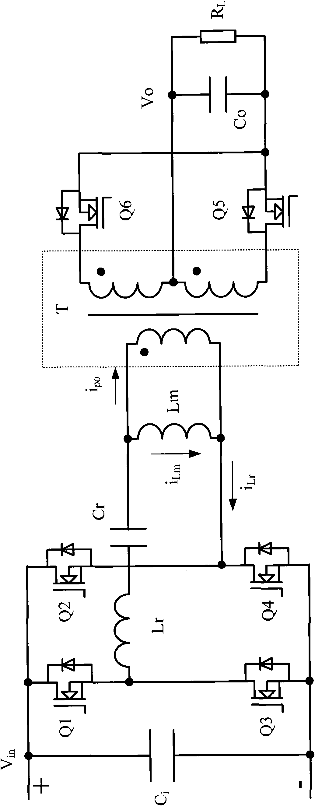
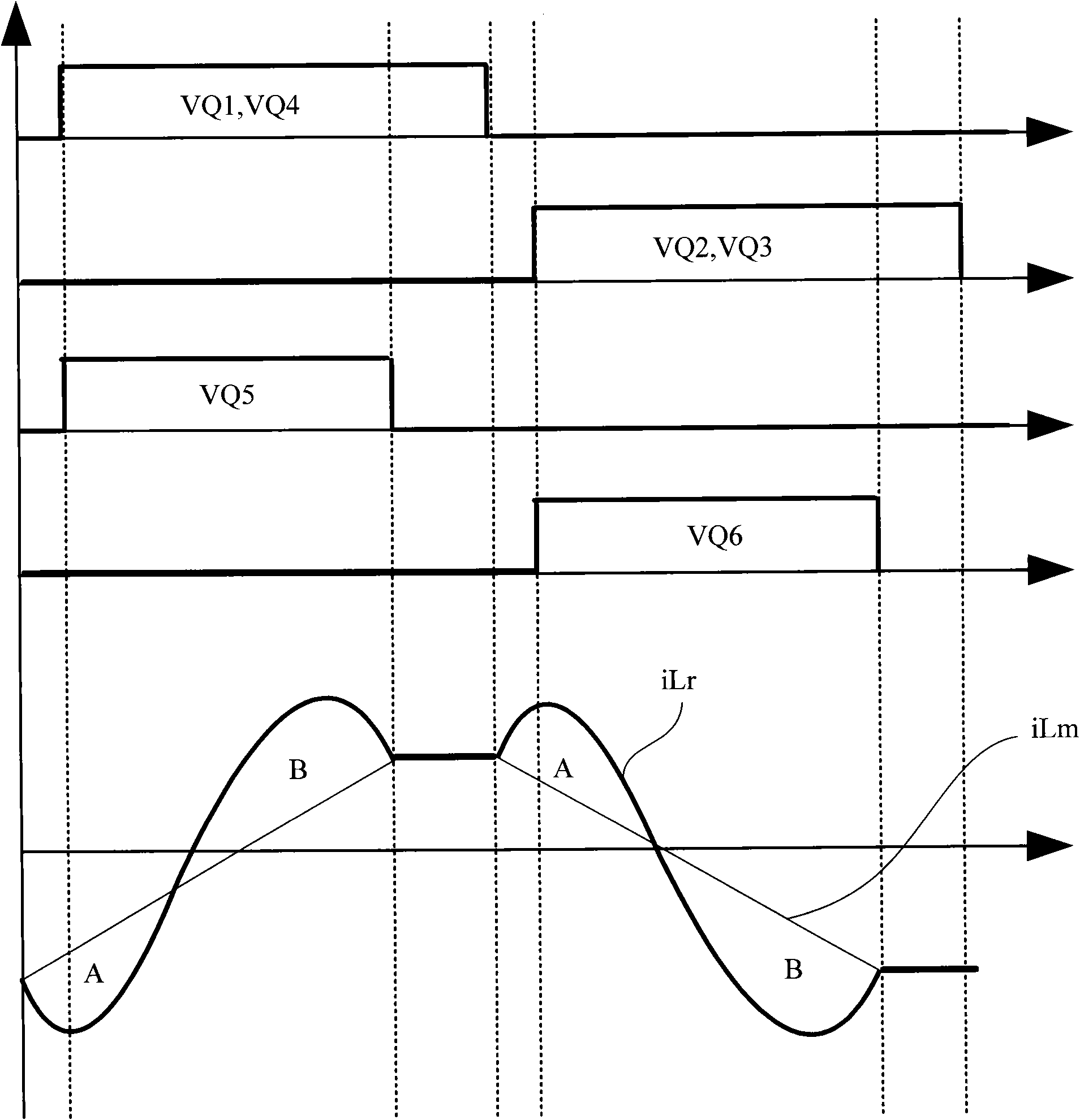
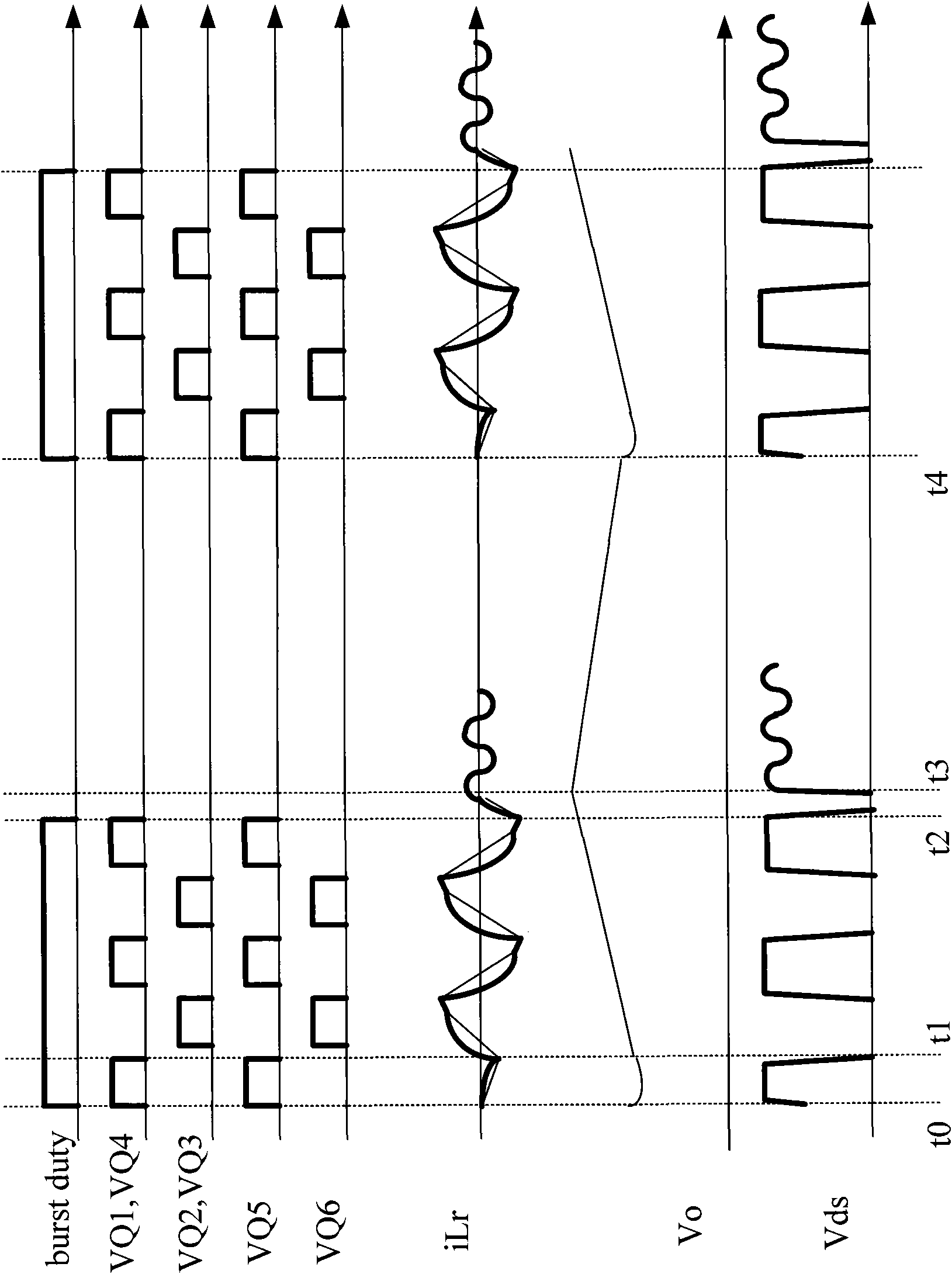
[0042] The new control method proposed by the present invention optimizes the secondary side synchronous rectification pulse signal of the resonant circuit operating in the intermittent mode. Since the resonant circuit stops working during the intermittent period, most of the energy in the resonant circuit will be consumed in the parasitic resistance through the free oscillation process during this period. The current iLr of the resonant inductor Lr and the voltage Vcr of the resonant capacitor Cr will return to near zero. . At the beginning of the next working process, due to the actions of the primary side switches Q1~Q4, the primary side power supply voltage Vin will be loaded onto the resonant circuit. At this time, the equivalent circuit of the circuit can be shown in Figure 4(a)-(b) Figure 4(a) is an equivalent circuit diagram of an LLC series resonant converter in the intermittent mode at the initial time of operation according to the concept of the present invention, Figur...


PUM


Abstract

The invention discloses a synchronous rectification circuit which comprises a converter and an intermittent mode controller, wherein the converter comprises a first synchronous rectification switch; and the intermittent mode controller comprises a logical flow module which is used for eliminating a first driving signal of a switch cycle of the first synchronous rectification switch. The synchronous rectification circuit and the control method thereof can be applied to a resonance converter circuit and a PWM converter circuit.

Description

Technical field [0001] The present invention relates to a working mode of a synchronous rectifier circuit with an intermittent mode controller, in particular to an LLC (dual inductance plus single capacitor) series resonant converter circuit with an intermittent mode controller and an intermittent mode controller Buck converter circuit. Background technique [0002] As the requirements for power density and circuit efficiency continue to increase, resonant converters have received more and more attention and applications due to their extremely high conversion efficiency. [0003] However, the light-load efficiency of the resonant converter cannot yet meet user requirements. This is because in order to achieve full soft switching, the resonant converter requires a certain amount of excitation current at light load, which will cause a certain amount of on-state loss and switching loss and other inherent losses. These losses are more important than heavy loads at light loads. The pr...

Claims


Application Information

Patent Timeline
IPC IPC(8): H02M3/28H02M7/12H02M3/335H02M7/23
CPCY02B70/1475Y02B70/10Y02P80/10
Inventor 王彬吴洪洋应建平辛晓妮吴其昆
Owner DELTA ELECTRONICS INC
Why Eureka
Try Eureka