Solar energy Stirling engine device

A Stirling engine, solar energy technology, applied in hot gas variable capacitance engine devices, solar thermal power generation, and mechanical power generation with solar energy, etc., can solve problems such as high cost and complex equipment, and achieve easy control, simple equipment, solar Use the effect of high efficiency

Inactive Publication Date: 2009-11-18
ZHEJIANG UNIV
View PDF0 Cites 16 Cited by
  • Summary
  • Abstract
  • Description
  • Claims
  • Application Information

AI Technical Summary

Problems solved by technology

This scheme is complicated i

Method used


Image

  • Solar energy Stirling engine device
  • Solar energy Stirling engine device

Examples


Embodiment 1

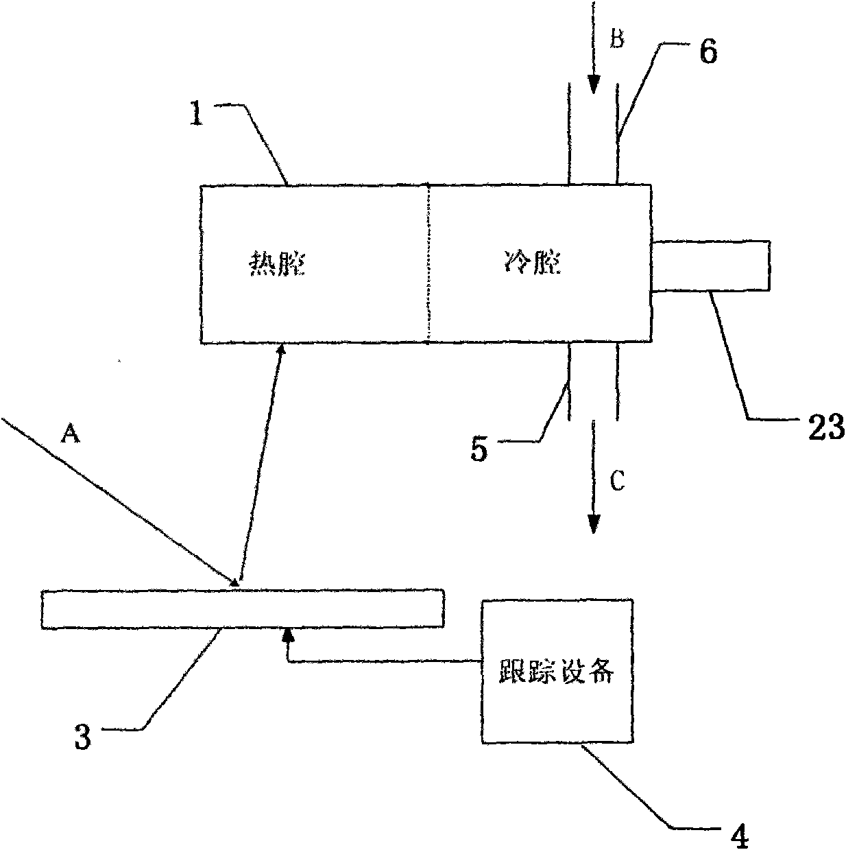
[0019] see figure 1 , a solar Stirling engine device, including a cylinder with a hot chamber and a cold chamber, a solar energy collection vacuum tube 1 as a hot chamber of the Stirling engine, and a closed cylinder of the Stirling engine together with the cold chamber.

[0020] Reflecting device 3 is used for sunlight collection; tracking device 4 is used for tracking solar energy. The sunlight is incident on the reflective device 3 along the direction A, and the reflective device 3 collects the sun's scattered light and direct light and reflects them to the solar vacuum heat collector 1; the tracking device 4 controls the angle and height of the reflective device 3, so that the reflective device 3 It can change with the morning and evening changes of the sun and the changes of the four seasons, so as to improve the collection efficiency of solar energy.

[0021] A water-cooling jacket with water inlet pipe 6 and water outlet pipe 5 is arranged on the periphery of the cold ...

Embodiment 2

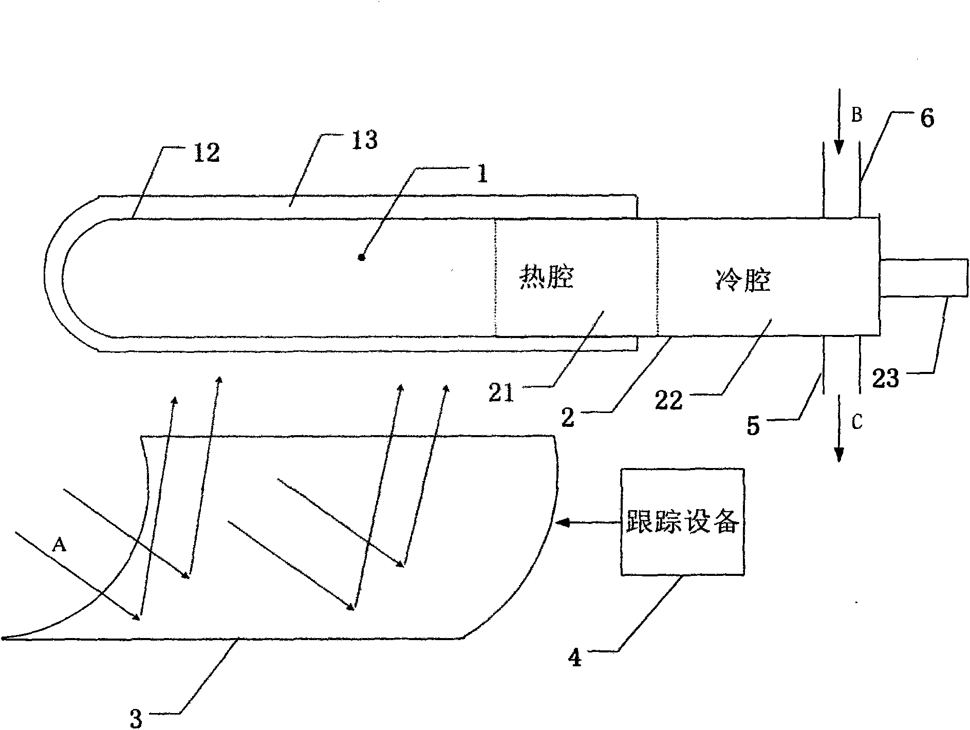
[0024] see figure 2 , a solar Stirling engine device, comprising a cylinder with a hot cavity and a cold cavity, and a solar energy collection vacuum tube 1 communicates with the thermal cavity 21 of the Stirling engine 2 as a part of the thermal cavity of the solar Stirling engine device of the present invention , constituting the hot cavity of the solar Stirling engine device of the present invention, and further together with the cold cavity 22 of the Stirling engine 2 constitutes the airtight cylinder of the solar Stirling engine device of the present invention. Between the double shells of the solar energy collection vacuum tube 1 is a vacuum chamber 13, the outer wall of the inner shell of the double shell is coated with a solar light absorbing coating 12, and the solar light absorbing coating 12 can further improve the solar energy of the solar energy collecting vacuum tube 1 collection ability.

[0025] Reflecting device 3 is used for sunlight collection; tracking de...


PUM


Abstract

The invention discloses a solar energy Stirling engine device, comprising a cylinder with a hot cavity and a cold cavity, wherein the hot cavity is a solar collecting vacuum tube, or is communicated with the solar energy collecting vacuum tube to absorb solar energy to heat the working medium by the solar collecting vacuum tube. The solar energy Stirling engine device utilizes renewable solar energy as the energy source of the engine, does not have waste gas emission and is environmentally friendly; the solar energy collecting vacuum tube is used as the hot cavity and a hot source acquiring device simultaneously, thus simplifying the device and being convenient to control; the invention is applied in solar energy generation; the solar energy Stirling engine device greatly reduces generation cost, provides hot water when the engine works, and has simple equipment and high solar energy utilization ratio.

Description

technical field [0001] The invention belongs to the field of development and utilization of new energy, in particular to a Stirling engine device utilizing solar energy. Background technique [0002] Various engine installations are known in the past, generally internal combustion engine installations utilizing petrol, diesel or natural gas as fuel. Different from the above-mentioned engine equipment, the Stirling engine belongs to the external combustion engine equipment, which has low noise during operation and can work quietly. The basic principle of the Stirling engine is to heat or cool the working medium (generally gas) sealed in the cylinder to generate pressure fluctuations and vertical motion of the piston, and then convert the vertical motion of the piston into rotational motion to achieve An engine device. The closed cylinder of the Stirling engine is filled with a certain volume of working fluid. One end of the cylinder is a hot chamber and the other end is a ...

Claims


Application Information

Patent Timeline
IPC IPC(8): F03G6/06F02G1/043
CPCY02E10/46
Inventor 王勇
Owner ZHEJIANG UNIV
Why Eureka
Try Eureka