

Metal surface treatment method
A surface treatment, metal technology, applied in metal material coating process, pressure inorganic powder coating, coating and other directions
- Summary
- Abstract
- Description
- Claims
- Application Information
AI Technical Summary
Problems solved by technology
Method used
Image

Examples
Embodiment 1
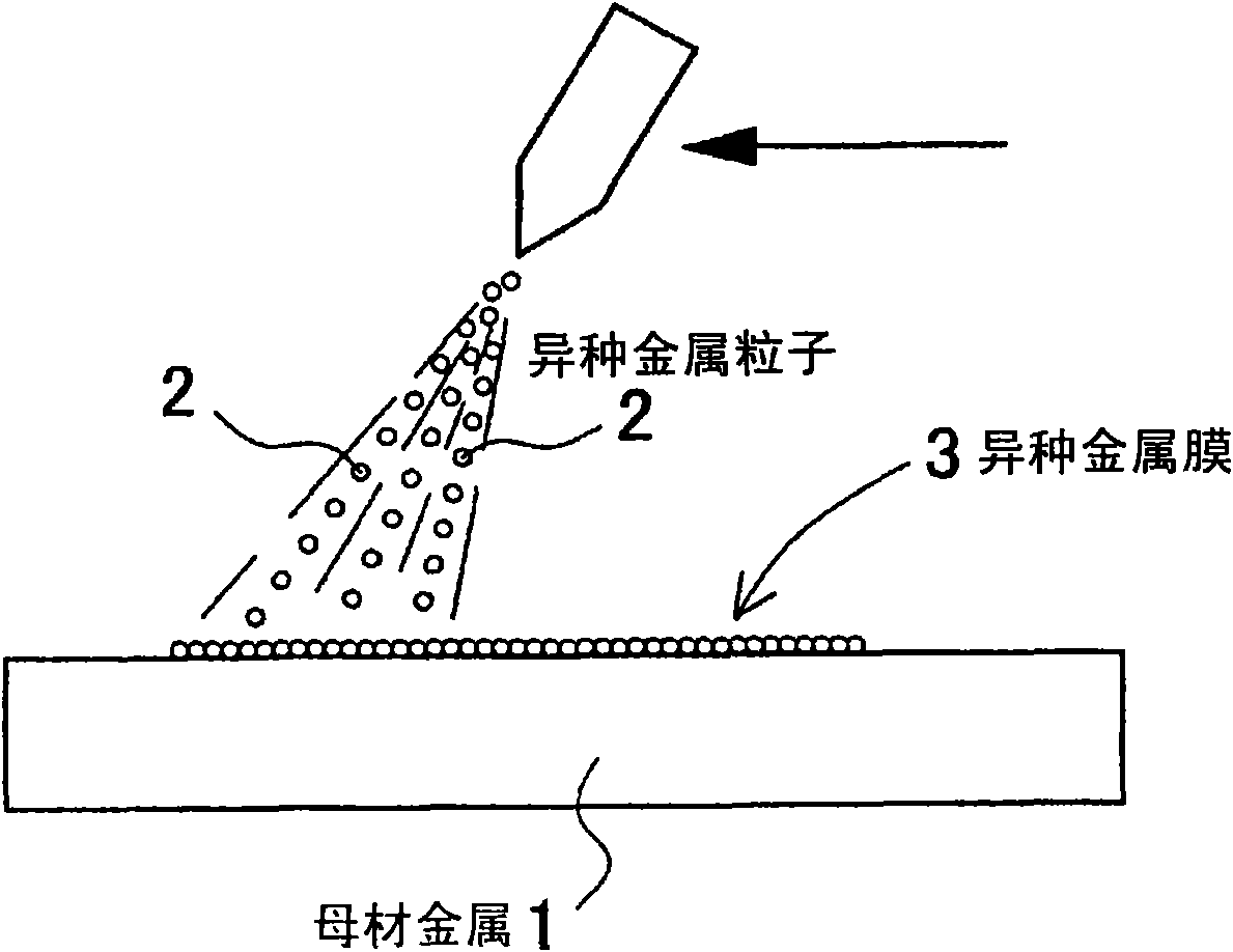
[0110] (1) Shot peening process
[0111] On the surface of pure copper or a copper alloy as a base metal 1, shot blasting is performed with dissimilar metal particles 2 composed of molybdenum disulfide. The average particle diameter of the dissimilar metal particles 2 was 10 μm, and the injection pressure of the shot blasting was 1 MPa. By this shot blasting, the dissimilar metal film 3 of molybdenum disulfide is formed on the surface of the base metal 1 .
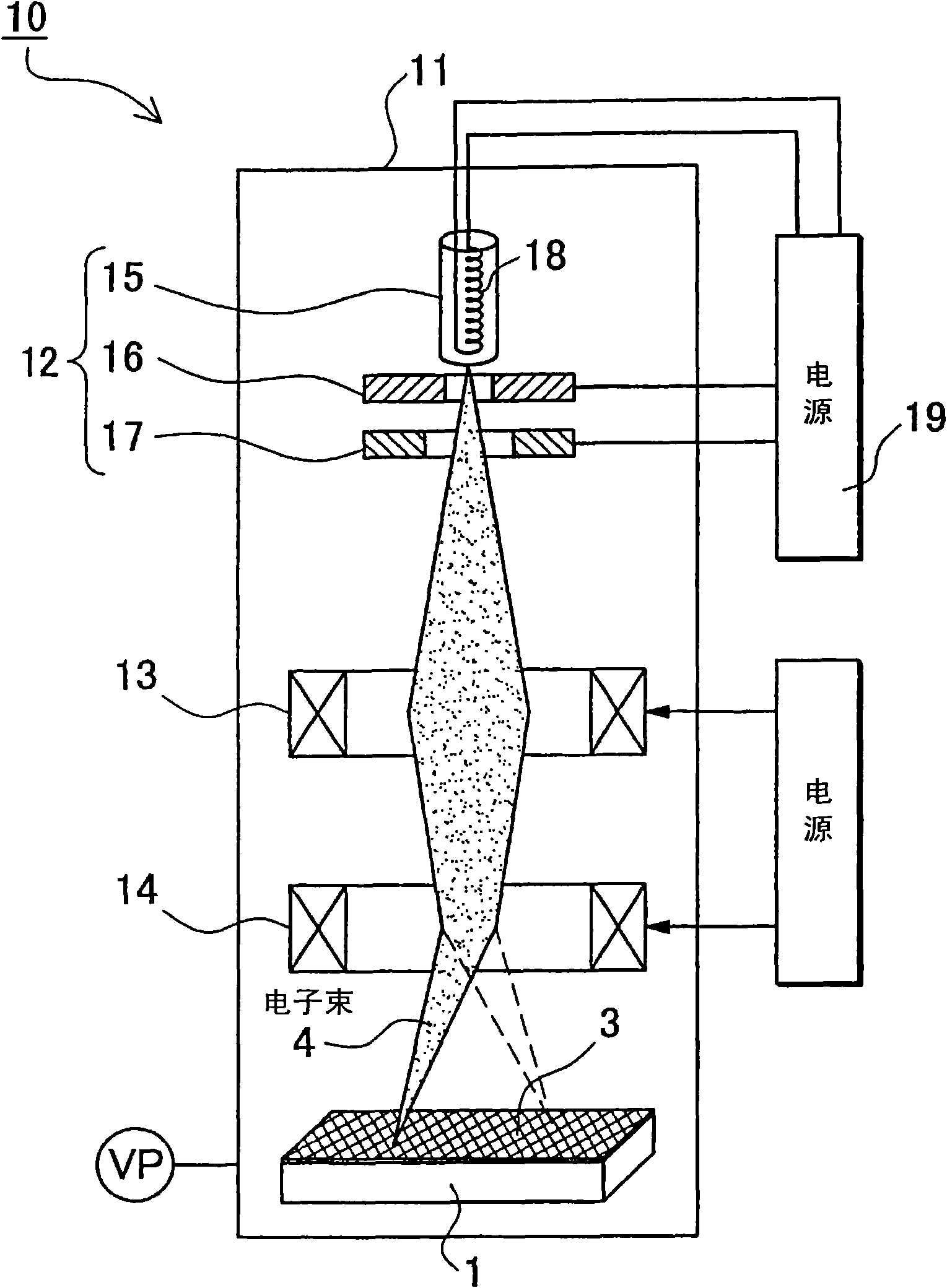
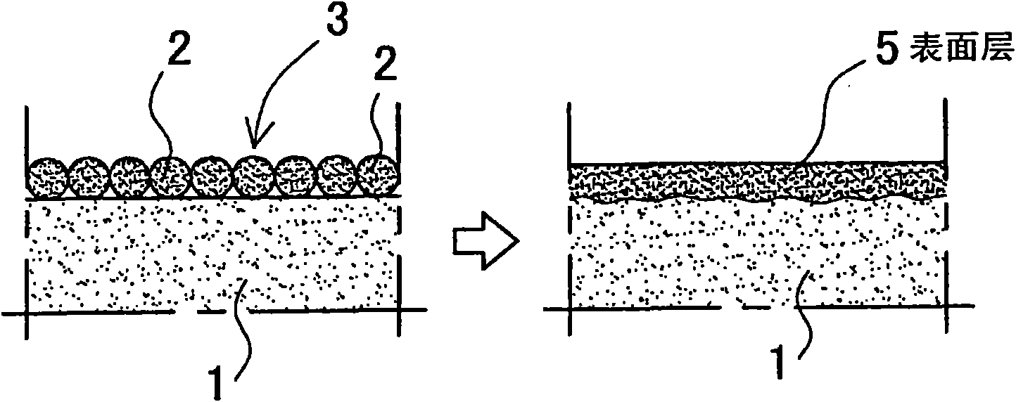
[0112] (2) Electron beam irradiation process
[0113] The base metal 1 having the dissimilar metal film 3 of molybdenum disulfide on its surface is placed in the sealed chamber 11, the sealed chamber 11 is evacuated to form a vacuum, and the surface of the base metal 1 is irradiated with an electron beam 4. Conditions for electron beam irradiation were set as follows. The vacuum degree of the airtight chamber 11 is 7 Pa or less.
[0114] Electron beam spot diameter 0.3mm
[0115] Acceleration voltage 30kV
[0116] Be...
Embodiment 2
[0122] (1) Shot peening process
[0123] Shot peening is performed on the Ti surface of the base metal 1 with tungsten dissimilar metal particles 2 . The average particle diameter of tungsten as the dissimilar metal particles 2 was 20 μm, and the injection pressure of the shot blasting was 1 MPa. By this shot blasting, the dissimilar metal film 3 of tungsten is formed on the surface of the base metal 1 .
[0124] (2) Electron beam irradiation process
[0125] A base metal 1 having a tungsten dissimilar metal film 3 on its surface is placed in a sealed chamber 11, the sealed chamber 11 is evacuated to form a vacuum, and the surface of the base metal 1 is irradiated with an electron beam 4. Conditions for electron beam irradiation were set as follows. The vacuum degree of the airtight chamber 11 is 7 Pa or less.
[0126] Electron beam spot diameter 0.3mm
[0127] Acceleration voltage 30kV
[0128] Beam current 110mA
[0129] The scanning area of the electron beam is 30m...
Embodiment 3
[0134] (1) Shot peening process
[0135] SKD-11 was used as the base metal 1, and shot blasting was performed with dissimilar metal particles 2 made of SiC. The average particle diameter of the dissimilar metal particles 2 was 3 μm, and the injection pressure of the shot peening was 1 MPa. By this shot blasting, the SiC dissimilar metal film 3 is formed on the surface of the base metal 1 .
[0136] (2) Electron beam irradiation process
[0137] A base metal 1 having a SiC dissimilar metal film 3 on its surface is placed in a sealed chamber 11 , the sealed chamber 11 is evacuated to form a vacuum, and the surface of the base metal 1 is irradiated with an electron beam 4 . Conditions for electron beam irradiation were set as follows. The vacuum degree of the airtight chamber 11 is 7 Pa or less.
[0138] Electron beam spot diameter 0.3mm
[0139] Acceleration voltage 30kV
[0140] Beam current 100mA
[0141] The scanning area of the electron beam is 30mm×30mm
[0142] S...
PUM
| Property | Measurement | Unit |
|---|---|---|
| particle size | aaaaa | aaaaa |
| particle size | aaaaa | aaaaa |
| particle size | aaaaa | aaaaa |
Abstract
Description
Claims
Application Information