Arrestor

A technology of lightning arrester and insulating sleeve, which is applied in the field of lightning arrester, can solve the problems of damage to lightning arrester components, difficulty in electric field concentration, etc., and achieve the effects of preventing dielectric breakdown, reducing weight, and reducing weight

Inactive Publication Date: 2009-11-25
SHOWA ELECTRIC WIRE & CABLE CO
View PDF2 Cites 7 Cited by
  • Summary
  • Abstract
  • Description
  • Claims
  • Application Information

AI Technical Summary

Problems solved by technology

[0005] First, because the potential distribution is determined by the positional relationship between the arrester element stack 130 and the shielding layer 150 (the shielding layer 150 is arranged on the outer periphery of the insulating sleeve 140), when the outer diameter of the insulating sleeve 140 is small, like Figure 12 As shown in the equipotential distribution diagram of , it is difficult to concentrate the electric field o

Method used


Image

  • Arrestor
  • Arrestor
  • Arrestor

Examples


Embodiment 1

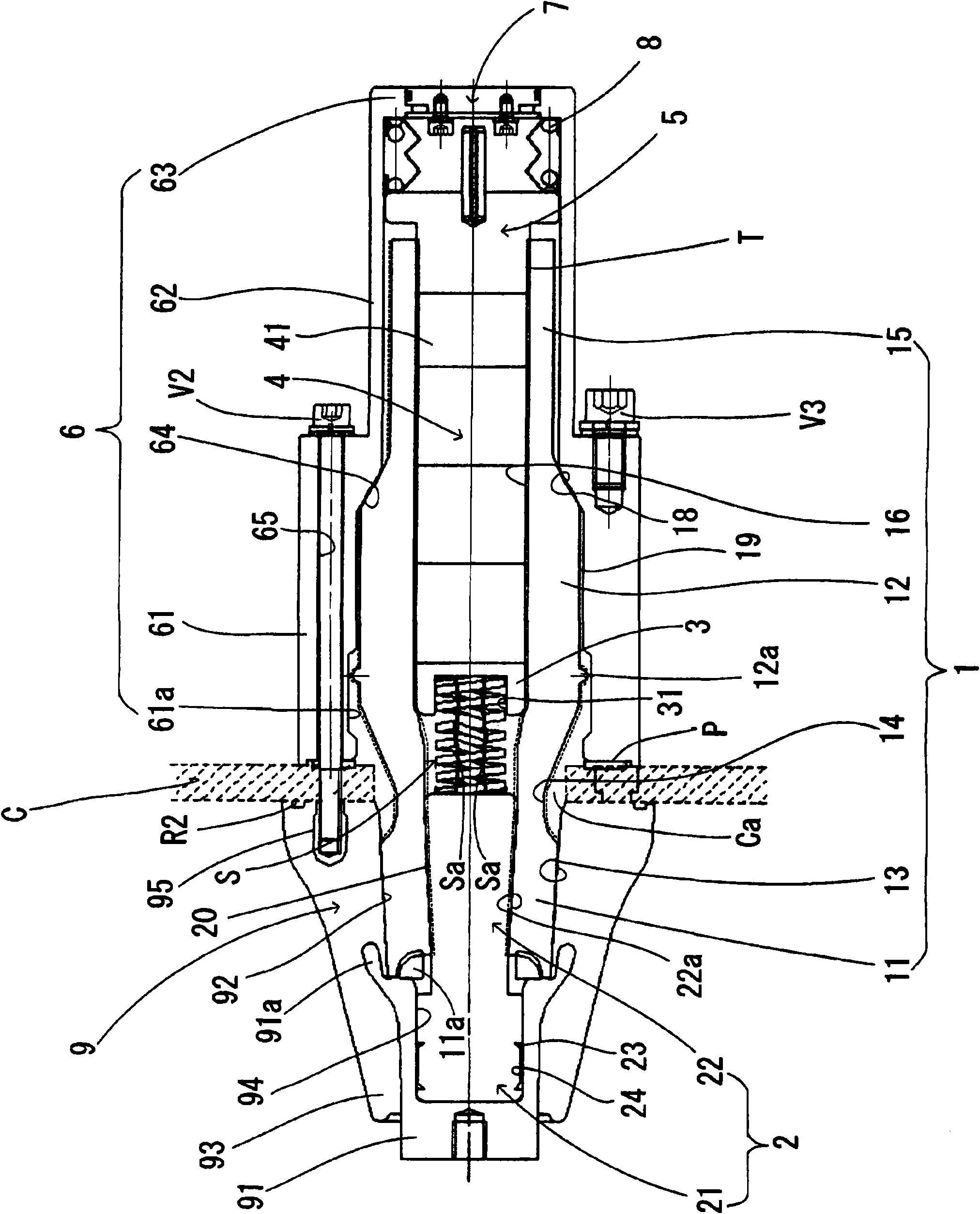
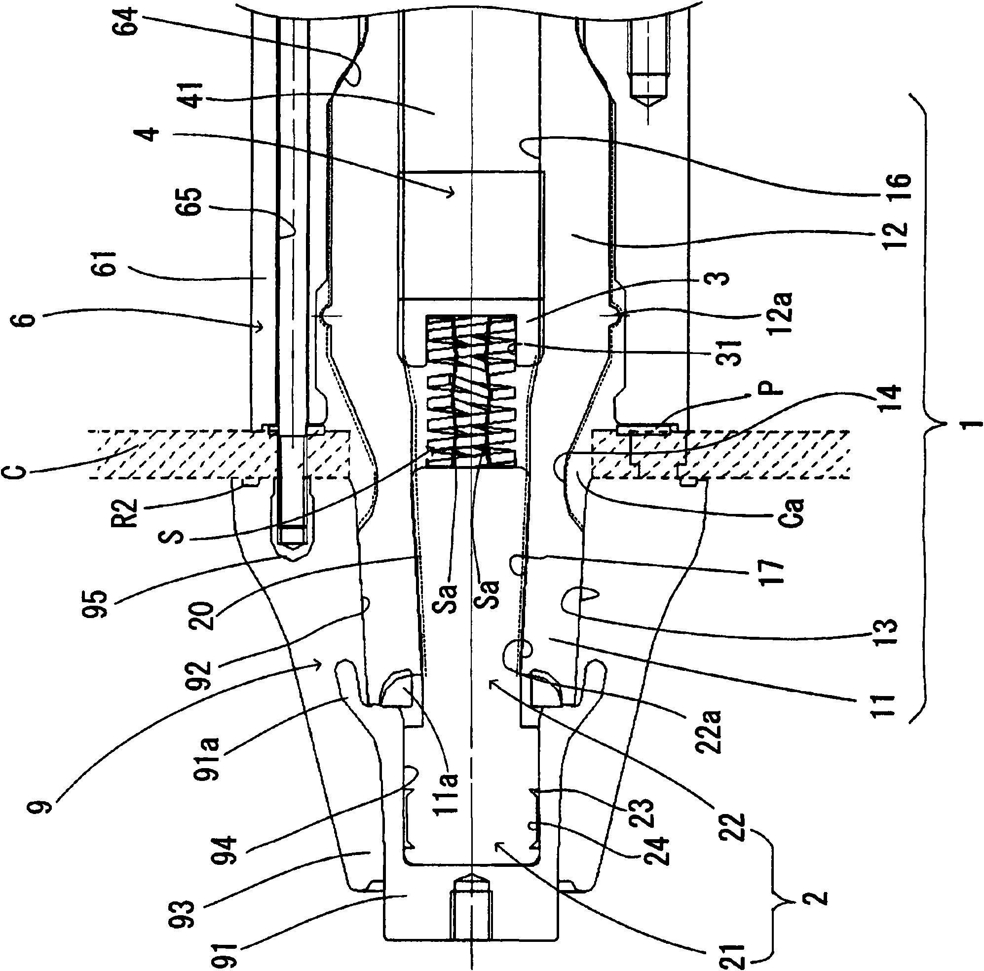
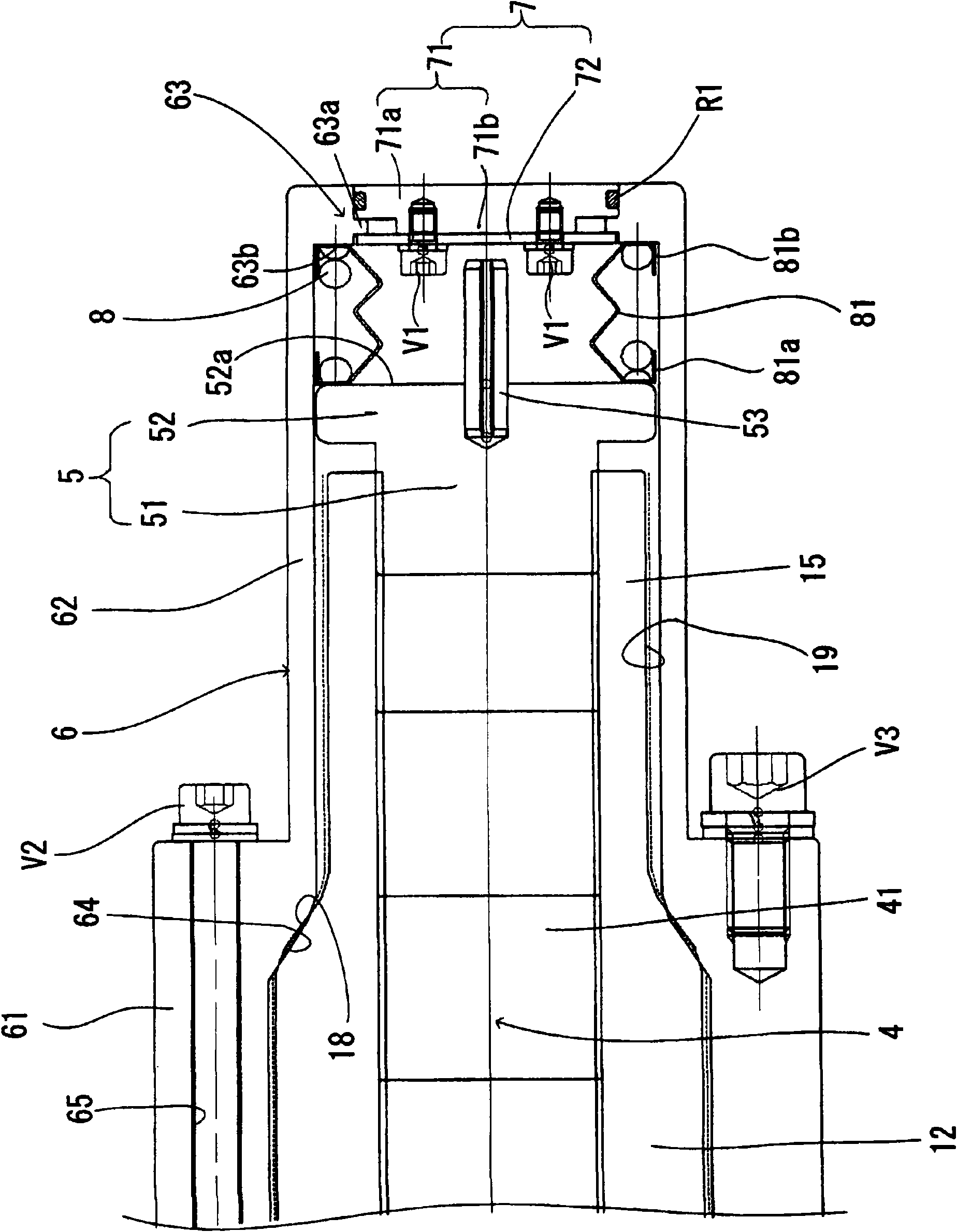
[0099] figure 1 is a partial sectional view showing an example of a 22kV class arrester in the first embodiment of the present invention, figure 2 Yes figure 1 An enlarged partial cross-sectional view of the front end portion of the arrester shown in , while image 3 Yes figure 1 An enlarged partial cross-sectional view of the rear end portion of the arrester shown in .

[0100] exist figure 1 Among them, the 22kV class arrester of the present invention is provided with an insulating sleeve 1, which includes a rubber-like elastic body such as silicon rubber, and a conductor 2 including, for example, an aluminum rod is arranged at the front end portion (high voltage side) of the aforementioned insulating sleeve 1 )11 center. In addition, a spindle-shaped larger-diameter portion 12 is arranged at the outer periphery of an almost central portion of the insulating sleeve 1, and a tapered outer surface 13 whose diameter gradually and smoothly becomes larger toward the rea...

Embodiment 2

[0131] Figure 5is a partial sectional view showing an example of a 22 kV class arrester in the second embodiment of the present invention. Furthermore, in this figure, the same reference numerals indicate figure 1 , and omit their detailed descriptions. In addition, in Figure 5 , for ease of understanding, omits the figure 1 The shielding layer 19 on the insulating sleeve 1 is shown in FIG.

[0132] In this example, if Figure 5 As shown in , by making the outer peripheral surface of the insulating sleeve 1 (especially the outer peripheral surface of the larger diameter portion 12 of the insulating sleeve 1, which has a higher electric field) and the inner surface of the corresponding position of the metal shell 6 The peripheral surfaces are in contact, which is configured such that no diameter difference occurs between the inner peripheral surface of the metal case 6 and the outer peripheral surface of the insulating sleeve 1 .

[0133] Here, the following describes...

Embodiment 3

[0139] Figure 7 is a partial sectional view showing an example of a 22 kV class arrester in the third embodiment of the present invention. Furthermore, in this figure, the same reference numerals indicate figure 1 , and omit their detailed descriptions. In addition, in Figure 7 , for ease of understanding, omits the figure 1 The shielding layer 19 on the insulating sleeve 1 is shown in FIG.

[0140] In this example, if Figure 7 As shown in , in the outer circumference of the insulating sleeve 1, especially in the outer circumference of the larger diameter portion 12 of the insulating sleeve 1 (the larger diameter portion 12 of the insulating sleeve 1 has a higher electric field), there is provided for The gap G (refer to Image 6 )'s inclusion F.

[0141] As such inclusions F, there may be, for example: a longitudinally arranged layer of a rubber band including, for example, butyl rubber (the longitudinally arranged layer is longitudinally arranged at the outer per...


PUM


Abstract

An arrestor in which surface pressure at the interface between the inner peripheral surface of a reception opening of a fixed bushing and the outer peripheral surface of the forward end of an insulation tube is maintained at an appropriate level. The arrestor has the insulation tube (1) having a conductor (2) at its forward end, a stacked body (4) of arrestor elements, inserted into the insulation tube (1) with a high-voltage electrode (3) in between, a ground electrode (5) placed at the rear end side of the arrestor element stacked body (4), a coiled spring (8) placed at the rear end side of the ground electrode (5) so as to be concentric with the insulation tube (1), a metal case (6) surrounding the insulation tube (1), the ground electrode (5), and the spring (8), and a sealing member (7) installed at the opening on the rear end side of the metal case (6). The outer diameter of the rear end side of the insulation tube (1) is set smaller than the outer diameter of the center portion of the insulation tube (1). Also, a tapered outer surface (13) is provided at the outer periphery of the forward end (11) of the insulation tube (1).

Description

technical field [0001] The invention relates to a lightning arrester. In particular, the present invention relates to a lightning arrester capable of attempting to miniaturize and reduce the weight of the insulating sleeve (which accommodates the stack of arrester elements), ensuring that the inner peripheral surface of the receiving opening of the fixed sleeve and the insulating sleeve interface pressure between the outer peripheral surfaces of the front end portion of the barrel, and prevent dielectric breakdown of the aforementioned interface. Background technique [0002] Generally, in gas insulated switchgears installed in power plants or substations, etc., lightning arresters are arranged to protect electrical equipment such as switchgears or transformers from abnormal voltages that would intrude through cables when, for example, lightning occurs. [0003] Therefore, as this surge arrester, such as Figure 11 As shown in , there is known a lightning arrester such that...

Claims


Application Information

Patent Timeline
IPC IPC(8): H02B13/02H01C7/12
CPCH01C7/123H01C7/126H01C7/12H02B13/02
Inventor 足立和久濑间信幸
Owner SHOWA ELECTRIC WIRE & CABLE CO
Why Eureka
Try Eureka