Reciprocating hydraulic bottom mud scraper

A mud scraper, reciprocating technology, applied in chemical instruments and methods, separation methods, precipitation separation, etc., can solve the problems of indurability, difficult maintenance, etc., and achieve long service life, easy maintenance, convenient and quick installation and adjustment. Effect

Inactive Publication Date: 2009-12-02
BEIJING WATERLINK ENVIRONMENT ENG
0 Cites 11 Cited by

AI-Extracted Technical Summary

Problems solved by technology

[0003] The invention provides a reciprocating hydraulic bottom mud scraper, which is used ...

Method used

Due to the lever power transmission structure in the embodiment of the present invention, scraper 31, scraper 32, the integral structure that the second push-pull rod 231 is welded into, and this structure has movable parts few, the characteristics of high transmission efficiency, so this The invention can realize the concentration and scraping effect of sludge, and the installation and adjustment are convenient and fast, the maintenance is simple, the operation is reliable, and the service life is long, thus solving the problem that the chain in the chain type sludge scraper is broken and loose, causing the entire sludge to be scraped The system is paralyzed, and it is difficult to repair and other problems.
In order to achieve better functions and effects, the mud scraping device 3 can be made of a scraper 31, a scraper 32 and a cushion welded together, wherein ...

Abstract

The invention discloses a reciprocating hydraulic bottom mud scraper, relates to the field of water purification and sewage treatment, and solves the problems that the prior mud scraper is difficult to maintain and is not durable. The reciprocating hydraulic bottom mud scraper comprises a power device (1), a lever power transmission system (2) and a mud scraping device (3) which are connected in turn, wherein the power device (1) is used for outputting power; the lever power transmission system (2) is used for transmitting the power output by the power device (1) to the mud scraping device (3); and the mud scraping device (3) is dragged by the lever power transmission system and does reciprocating motion at the bottom of a pool body to remove mud. Because the reciprocating hydraulic bottom mud scraper provides the lever power transmission system to replace a drag chain structure in the prior art, the structure of the lever power transmission system has the advantages of convenient and quick installation and adjustment, simple and convenient maintenance, reliable operation, long service life and the like relative to the drag chain structure.

Application Domain

Technology Topic

Image

  • Reciprocating hydraulic bottom mud scraper
  • Reciprocating hydraulic bottom mud scraper
  • Reciprocating hydraulic bottom mud scraper

Examples

  • Experimental program(3)

Example Embodiment

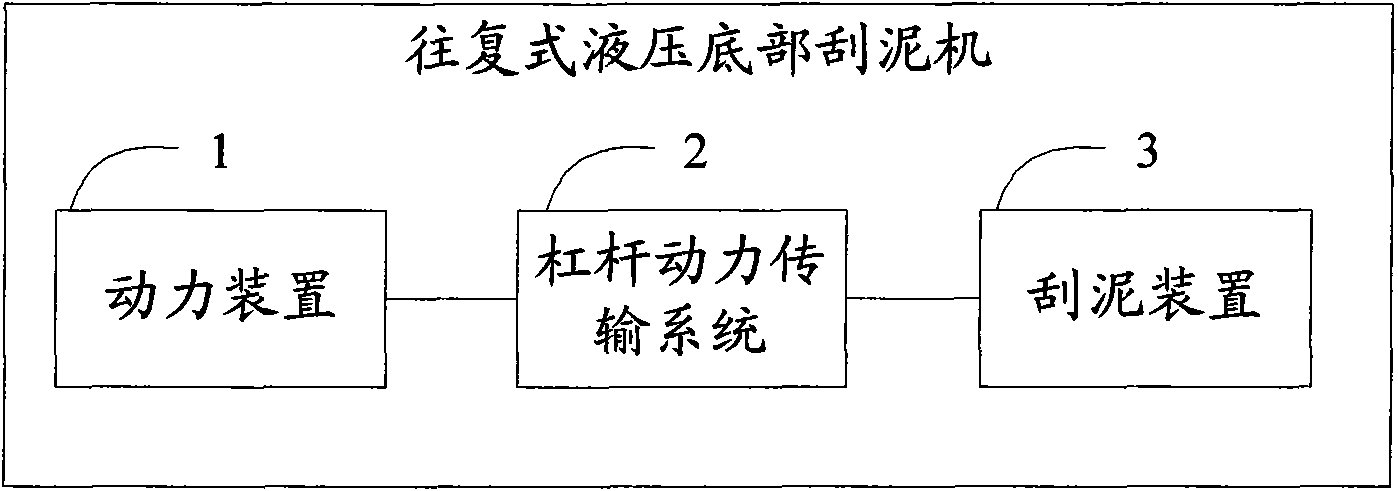
[0021] Embodiment 1, see figure 1 As shown, it includes: a power device 1 , a lever power transmission system 2 and a mud scraping device 3 connected in sequence.
[0022] Among them, the power device 1 is used to output power, which can be a cylinder device or a motor device. In practical applications, the sedimentation tank with a size of more than 250 square meters is driven by hydraulic pressure, and the sedimentation tank with a size of less than 250 square meters is directly driven by an electric motor.
[0023] The lever power transmission system 2 is used to transmit the power output by the power device 1 to the mud scraping device 3 .
[0024] The mud scraping device 3 is pulled by the lever power transmission system 2, and reciprocates at the bottom of the pool body to remove sludge.

Example Embodiment

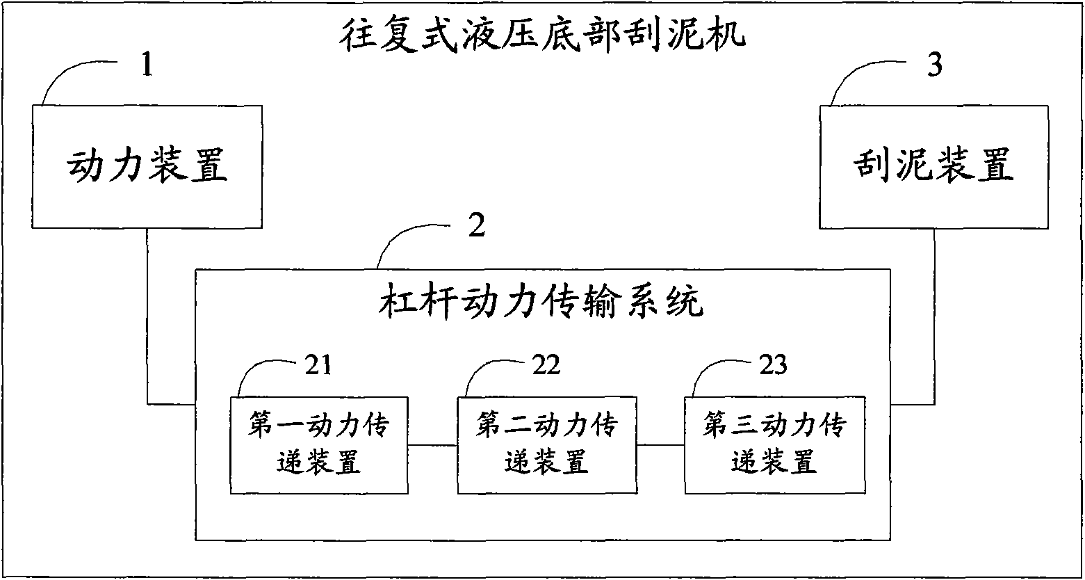
[0025] Embodiment 2, this embodiment further refines the lever power transmission system 2 in Embodiment 1, see figure 2 As shown, it includes: a power device 1 , a lever power transmission system 2 and a mud scraping device 3 connected in sequence.
[0026] Among them, the power device 1 is used to output power, which can be a cylinder device or a motor device. In practical applications, the sedimentation tank with a size of more than 250 square meters is driven by hydraulic pressure, and the sedimentation tank with a size of less than 250 square meters is directly driven by an electric motor.
[0027] The lever power transmission system 2 specifically includes: a first power transmission device 21 for transmitting the power output by the power device 1; a second power transmission device 22 for turning the direction of the power transmitted by the first power transmission device 21, turning The final power direction is generally consistent with the moving direction of the mud scraping device 3; the third power transmission device 23 is used for pulling the mud scraping device 3 with the power transmitted by the second power transmission device 22.
[0028] The mud scraping device 3 is pulled by the lever power transmission system 2, and reciprocates at the bottom of the pool body to remove sludge.

Example Embodiment

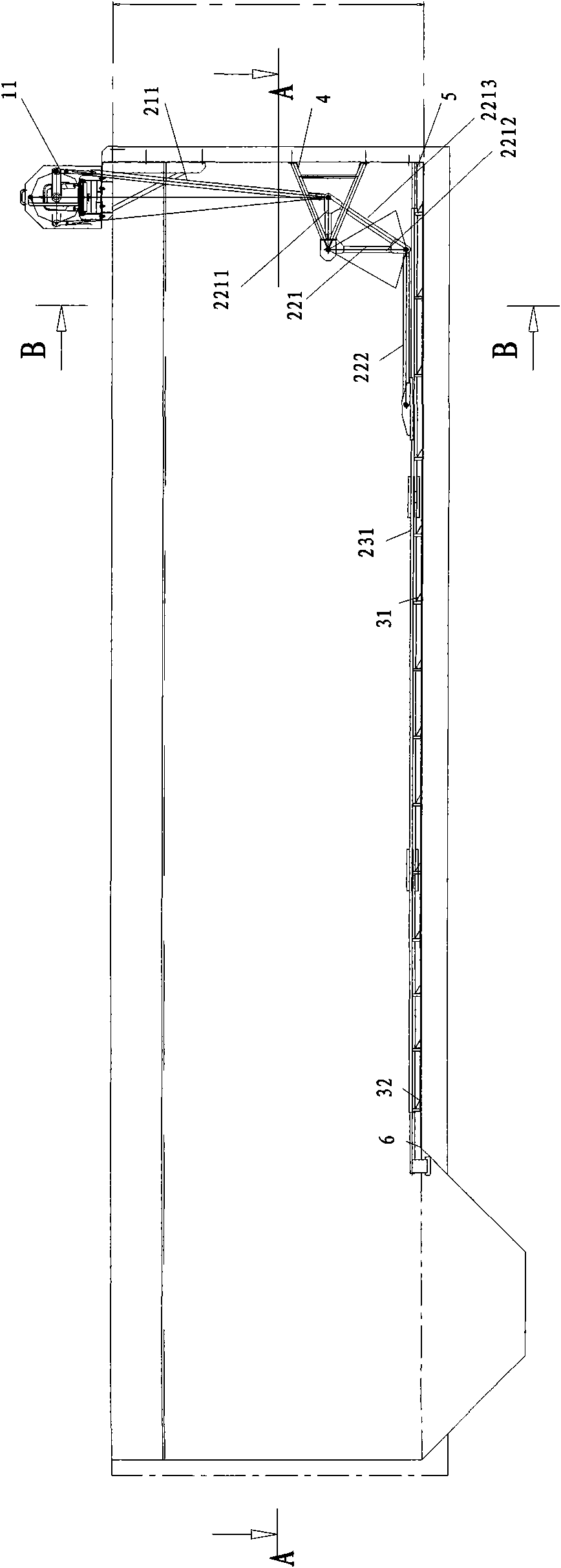
[0029] Embodiment 3. This embodiment further refines the first, second, and third power transmission devices and mud scraping devices in the lever power transmission system 2 in embodiment 2. See image 3 , 4 , 5, 6, 7, 8, including: cylinder device 11, first push-pull rod 211, angle arm support frame 4, angle arm 221, link arm 222, second push-pull rod 231, guide rod 5, scraper 31, Scraper 32, bottom surface slide rail 6. It is mainly powered by the cylinder device 11, the first power transmission device 21 is made by the first push-pull rod 211, the second power transmission device 22 is made by the angle arm 221 and the link arm 222, and the third power transmission device is made by the second push-pull rod 231 The device 23, the scraper 31 and the scraper 32 are the mud scraping device 3 for the final mud scraping action. Wherein the corner arm support frame 4 is fixed on the pool wall, plays the role of fixing the corner arm 221, one end of the guide rod 5 is fixed on the pool wall, and the other end is sleeved in the second push-pull rod 231, and plays the role of guiding the movement of the second push-pull rod 231 . Wherein the angular arm 221 is made up of a horizontal pipe 2211, a vertical pipe 2212, and an inclined pipe 2213 in proportion, the horizontal pipe 2211 and the vertical pipe 2212 are connected in the angular arm support frame 4, the vertical pipe 2212 and the inclined pipe 2213 Connected to one end of the link arm 222 , the horizontal tube 2211 and the inclined tube 2213 are connected to one end of the first push-pull rod 211 . Wherein the scraper 31 is welded on the scraper 32, and the second push-pull rod 231 is welded on the scraper 31, and the three constitute one body to move on the bottom slide rail 6. One end of the second push-pull rod 231 is connected to the link arm 222 , and the other end is sleeved on the guide rod 5 .
[0030] In order to achieve better functions and effects, the mud scraping device 3 can be composed of a scraper 31, a scraper 32 and a cushion layer welded together, wherein the structure of the scraper 31: there is an inclined flat surface 311 in the cross section, a vertical A concave surface 312 and a flat surface 313 with a hollow bottom, the concave surface 312 of which faces the forward conveying direction (ie, faces the sludge conveying direction). exist Figure 9 , 10 In , the relationship between the projected lengths of these surfaces is constructed in a certain scale. The hollow bottom surface and generally inclined flat surface can effectively save energy consumption, and at the same time, the generally vertical concave surface can better restrain the bottom sludge from rising, so as to play the role of the sludge scraper more effectively. Therefore, compared with the prior art, the utility model has the advantages of reasonable structure, convenient installation and adjustment, easy maintenance, reliable operation and long service life.
[0031] In the specific implementation process based on the above-mentioned embodiment of the present invention, it includes cylinder full stroke and cylinder full return stroke in two parts:
[0032] see Figure 9 As shown, under the full stroke, the cylinder pushes down the first push-pull rod 211, and the first push-pull rod 211 transmits power to the angle arm 221 and the link arm 222 as the first power transmission device 21, so that the angle arm 221, the link arm 222 Rotate, angle arm 221 and link arm 222 transmit power to the second push-pull rod 231 as the second power transmission device 22, scraper 31, scraper 32, wherein the second push-pull rod 231 moves forward along the vertical plane of scraper 31, completes this The process takes 25-35 seconds, and the mud in the bottom of the pool forms a vortex along the vertical surface 312 of the scraper to thicken the sludge.
[0033] see Figure 10 As shown, the cylinder pulls up the first push-pull rod 211 under the full return stroke, and the first push-pull rod 211 transmits power to the angular arm 221 and the link arm 222 as the first power transmission device 21, so that the angular arm 221 and the link arm 222 rotate , the angular arm 221 and the link arm 222 transmit power to the second push-pull rod 231 as the second power transmission device 22, the scraper 31, and the scraper 32, wherein the second push-pull rod 231 moves forward along the inclined plane 311 of the scraper to complete this The process needs 10-15 seconds, and the return speed of the scraper 31 is 2-3 times of the forward speed of the scraper 31, so that the mud in the bottom of the pool is turned forward along the inclined plane 311 of the scraper.
[0034] Under the reciprocating action of this process, the sludge in the bottom of the pool is continuously concentrated and turned forward, thereby scraping the sludge in the bottom of the pool.

PUM

no PUM

Description & Claims & Application Information

We can also present the details of the Description, Claims and Application information to help users get a comprehensive understanding of the technical details of the patent, such as background art, summary of invention, brief description of drawings, description of embodiments, and other original content. On the other hand, users can also determine the specific scope of protection of the technology through the list of claims; as well as understand the changes in the life cycle of the technology with the presentation of the patent timeline. Login to view more.

Similar technology patents

Tunneling machine and auxiliary excavation device for tunneling machine

PendingCN113898359AEasy to install and adjustGood stabilityTunnelsPhysicsTunnel boring machine
Owner:CHINA RAILWAY ENGINEERING EQUIPMENT GROUP CO LTD

Installation bracket for outdoor electrical equipment

PendingCN111412345AEasy to install and adjustStands/trestlesStructural engineeringElectric power equipment
Owner:杭州粒合信息科技有限公司

Assembled tunnel bracket

Owner:SHENZHEN POWER SUPPLY PLANNING DESIGN INST

Classification and recommendation of technical efficacy words

  • Easy maintenance
  • Easy to install and adjust

High clearance vehicle

InactiveUS6454294B1Big gapEasy maintenanceAgricultural machinesVehicle body-frame connectionsSpray nozzleHinge angle
Owner:CNH IND AMERICA LLC

Large-size multi-axis-linkage electrolytic machine tool

ActiveCN103464845ALarge operating spaceEasy to install and adjustMachining working media supply/regenerationElectric circuitsMachine toolPulse power supply
Owner:NANJING UNIV OF AERONAUTICS & ASTRONAUTICS
Why Eureka
Try Eureka