
Dielectric resonance UHF RFID label antenna provided with T-shaped matching network

A medium resonance, tag antenna technology, applied in the field of radio frequency identification electronic tag antenna, can solve the problems of performance deterioration, short reading distance, low antenna gain, etc., and achieve the effect of reducing the size of the antenna, improving the reading distance, and high radiation efficiency

Inactive Publication Date: 2009-12-02
SOUTH CHINA UNIV OF TECH
View PDF0 Cites 23 Cited by
  • Summary
  • Abstract
  • Description
  • Claims
  • Application Information

AI Technical Summary

Problems solved by technology

[0005] Second, application environment issues
Different dielectric properties of items will cause varying degrees of deterioration in the performance of RFID tag antennas
In particular, the performance deterioration caused by metal items is particularly serious, which will cause the RFID tag to be unrecognizable and reduce the success rate of the RFID system for identifying items
However, the traditional flexible board antenna cannot work on the metal surface, which requires the design of an antenna RFID tag antenna that can work on the metal surface
[0006] Third, miniaturization and reading distance issues
The tag antenna is generally small in size, and its gain is generally low. Although the currently used microstrip antenna can work on metal surfaces, the gain of the antenna is low under the requirement of miniaturization, and its reading distance is relatively short.

Method used


Image

  • Dielectric resonance UHF RFID label antenna provided with T-shaped matching network
  • Dielectric resonance UHF RFID label antenna provided with T-shaped matching network
  • Dielectric resonance UHF RFID label antenna provided with T-shaped matching network

Examples


Embodiment Construction

[0027] specific implementation plan

[0028] The present invention will be described in further detail below in conjunction with the accompanying drawings, but the scope of protection claimed by the present invention is not limited to the scope of the following examples.

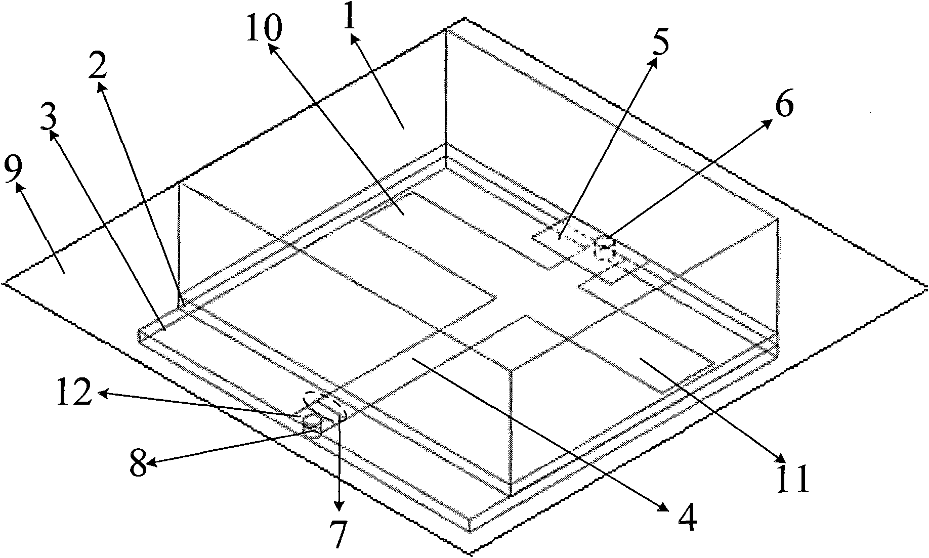
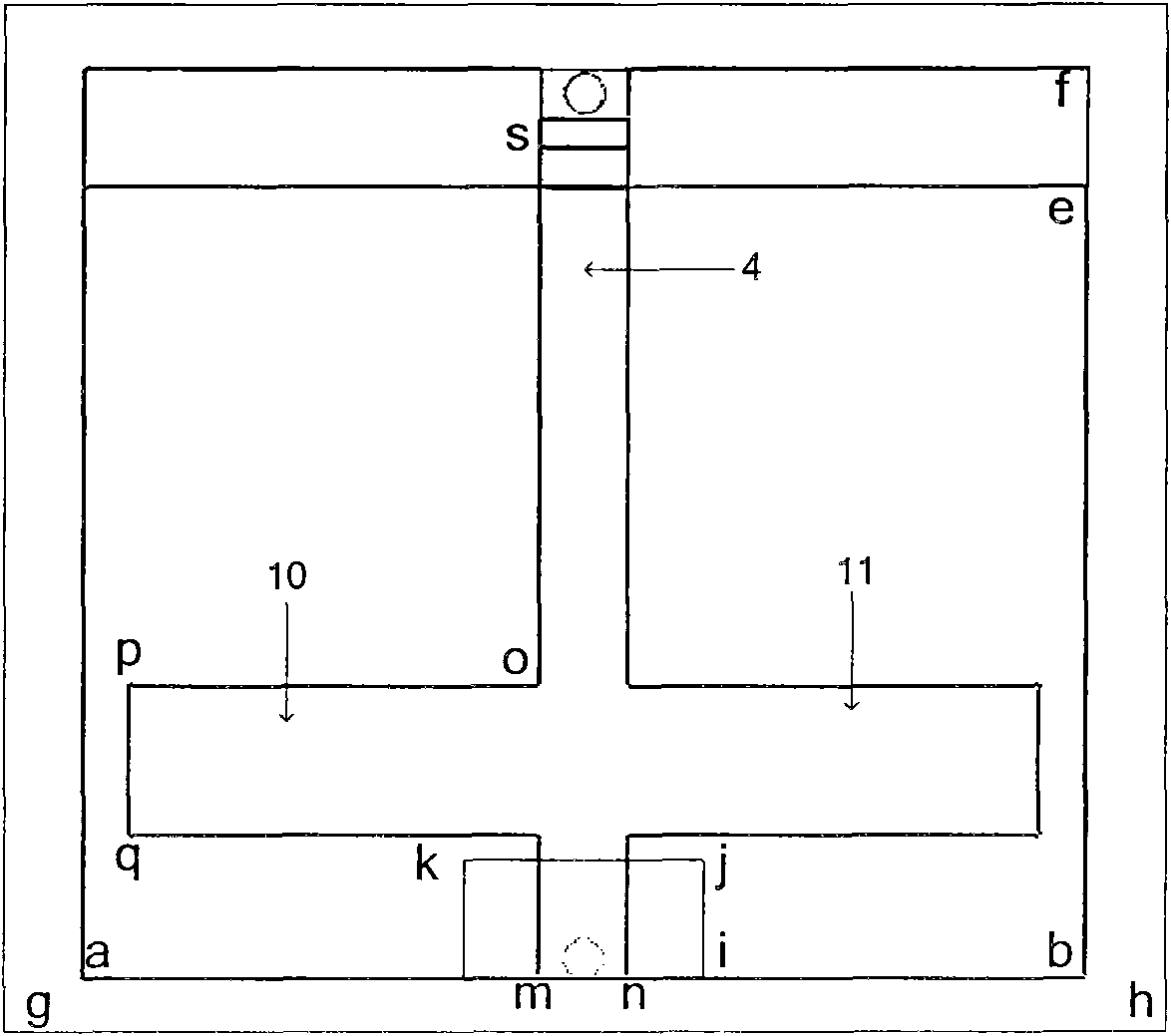
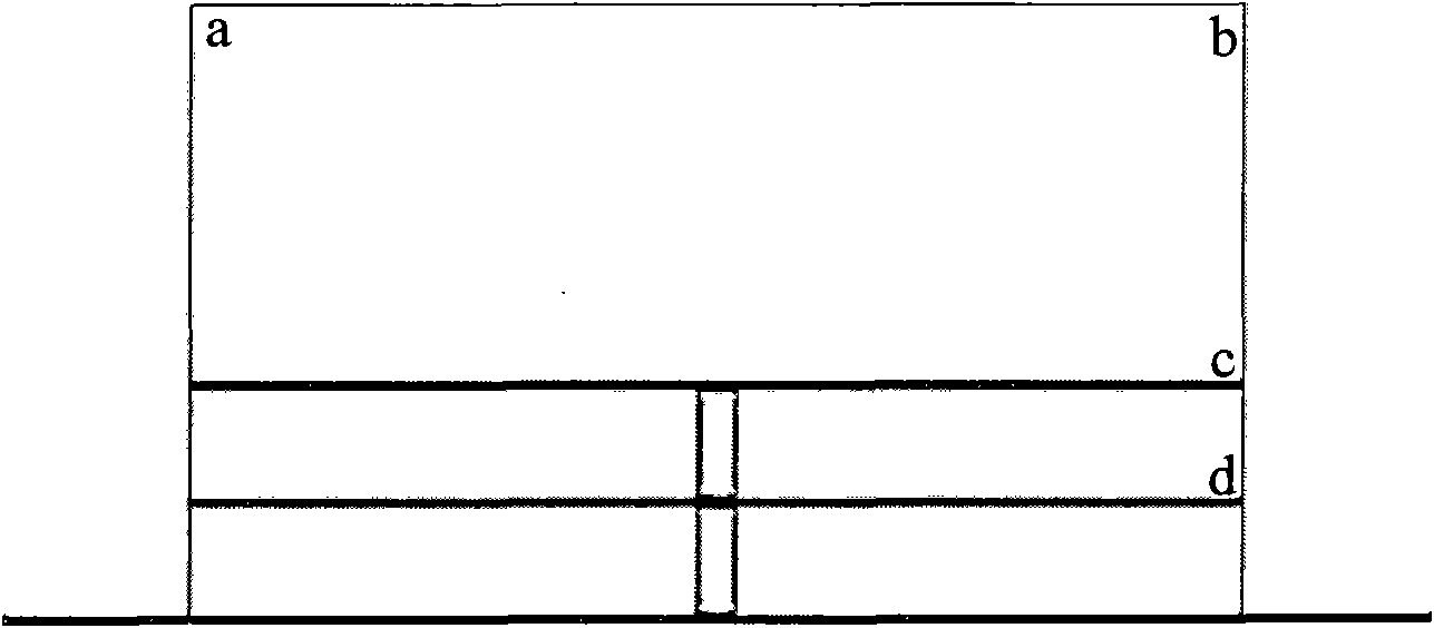
[0029] Such as figure 1 , figure 2 and image 3 As shown, the dielectric resonant UHF RFID tag antenna with a T-shaped matching network includes an upper dielectric resonator 1 , a middle dielectric substrate 2 , a lower dielectric substrate 3 and a bottom copper floor 9 .

[0030] The resonant frequency of the antenna is mainly obtained by adjusting the side length ab, thickness bc and the dielectric constant of the upper dielectric resonator 1 . The larger the side length ab, the thickness bc and the dielectric constant, the smaller the resonant frequency; otherwise, the larger the resonant frequency. In order to make the invention work in the UHF frequency band, and have the characteristics of small ...


PUM

PropertyMeasurementUnit
Side lengthaaaaaaaaaa
Thicknessaaaaaaaaaa
Widthaaaaaaaaaa

Abstract

The invention discloses a dielectric resonance UHF RFID label antenna provided with a T-shaped matching network, which comprises an upper layer dielectric resonator, a middle layer dielectric substrate, a lower layer dielectric substrate and a bottom layer copper sheet floorboard, wherein a copper sheet feeder line is arranged between the upper layer dielectric resonator and the middle layer dielectric substrate, a microstrip matched line is arranged between the middle layer dielectric substrate and the lower layer dielectric substrate, the microstrip matched line and an open circuit short-circuit line form the T-shaped matching network, the copper sheet feeder line is connected with the microstrip matched line through a via hole, the via hole passes through the lower layer dielectric substrate and is connected with the bottom layer floorboard, and a feeding port is connected with an RFID label chip. The dielectric resonance UHF RFID label antenna can work in a radio frequency recognition system at a UHF frequency band with the bandwidth covering 866 to 869 MHz or 902 to 928 MHz, not only can conveniently achieve the impedance matching between the chip and the antenna, but also can be conveniently applied to multi-application environments of metal surfaces and the like, and has the characteristics of small volume, high gain, easy processing and low cost.

Description

technical field [0001] The present invention relates to a radio frequency identification electronic tag antenna, in particular to a high-gain radio frequency identification electronic tag which can be applied in the UHF frequency band, that is, in the 860MHz-960MHz frequency band, has a T-shaped matching network, and can be conveniently applied to metal surfaces antenna. Background technique [0002] Radio Frequency Identification (RFID) technology is an automatic identification technology that conducts non-contact two-way data communication through radio frequency to identify targets and obtain relevant information. Radio frequency identification technology (RFID) has been rapidly promoted in recent years, and is widely used in logistics, warehouses and other occasions for item identification, helping such industries to collect and manage item information in an informatized and high-speed manner, so as to achieve high efficiency of items management and scheduling. The rad...

Claims


Application Information

Patent Timeline
IPC IPC(8): H01Q1/24H01Q13/08G06K19/07
Inventor 胡斌杰尹以雁
Owner SOUTH CHINA UNIV OF TECH
Learn More