
Plate stretch-forming machine

A drawing machine and plate technology, applied in the field of mechanical engineering, can solve the problems of uneven distribution of tensile stress and tensile strain of parts, lower material utilization rate, and high manufacturing cost, so as to improve material utilization rate, reduce manufacturing cost, and reduce load. The effect of reasonable path

Active Publication Date: 2009-12-09
JILIN UNIV
View PDF0 Cites 22 Cited by
  • Summary
  • Abstract
  • Description
  • Claims
  • Application Information

AI Technical Summary

Problems solved by technology

After the clamps of the traditional drawing machine clamp the sheet, with the cooperation of the drawing die, each part of the sheet is basically stretched along the longitudinal direction synchronously. When forming a double curvature skin part, the distribution of tensile stress and tensile strain of the part is obviously uneven. It is easy to produce forming defects such as not sticking to the mold, cracking or wrinkling
In order to eliminate defects, blanks for drawing often require a large process margin, which reduces the utilization rate of materials
In addition, the currently commonly used stretching machine uses a multi-axis hydraulic servo control system, resulting in expensive manufacturing costs

Method used


Image

  • Plate stretch-forming machine
  • Plate stretch-forming machine
  • Plate stretch-forming machine

Examples


Embodiment Construction

[0042] The specific content and working process of the present invention will be further described below in conjunction with the embodiments shown in the accompanying drawings.

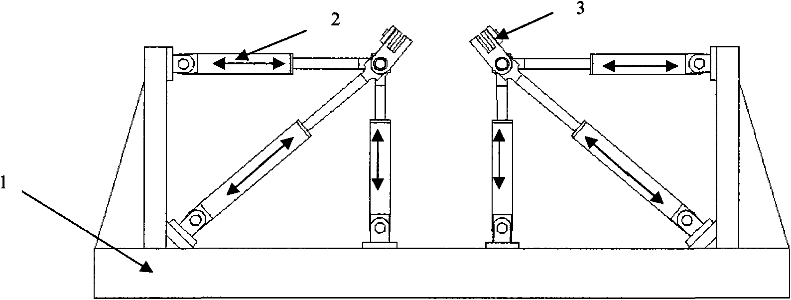
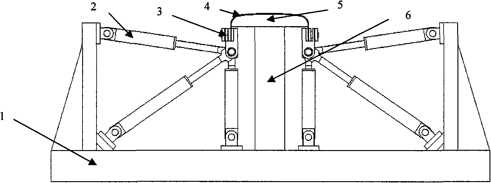
[0043] Fig. 1 is a schematic diagram of a drawing machine, which is mainly composed of a frame 1 and a row of five pulling mechanisms and clamping mechanisms 3 on the left and right sides of the frame 1. The material pulling mechanism is made up of three hydraulic cylinders 2, one is arranged horizontally, one is arranged vertically, and the other is arranged obliquely. One end of the hydraulic cylinder 2 is respectively hinged with the frame 1, and the other end is jointly hinged with the clamping mechanism 3. By changing the hydraulic pressure of the hydraulic cylinder 2, the stroke of the hydraulic cylinder 2 can be changed, and the angle between the hydraulic cylinders 2 can also be changed, thereby changing the position and the pulling direction of the clamping mechanism 3. The hydraulic pressur...


PUM


Abstract

A plate stretch-forming machine of the invention relates to plastic processing equipments used for 3-D curved surface forming of plates and belongs to the mechanical engineering field. The machine aims at facilitating tensile stress and tensile strain distribution of stretch-forming parts to be even, realizing stretch-forming of curved parts with big curvature, improving stretch-forming quality and material utilization ratio and reducing manufacturing cost of stretch-forming devices. The machine mainly comprises a rack (1), a row of multiple material-pulling mechanisms and a row of multiple material-chucking mechanisms (3), which are arranged at the left and right sides of the rack (1) respectively; the material-pulling mechanism is formed by mutual hinge joint of three hydraulic cylinders (2), wherein, one of the three hydraulic cylinders (2) is horizontally arranged, one vertically arranged and one obliquely arranged; the material-chucking mechanism is mainly composed of a support (10), a material-chucking plate (11) and a small-stroke single-acting hydraulic cylinder (12).

Description

Technical field: [0001] Plate drawing machine is a plastic processing equipment used for three-dimensional curved surface forming of plate parts, which belongs to the field of mechanical engineering. Background technique: [0002] Stretching machine is a device for stretching and deforming plates, and is mainly used in the forming of double curvature skin parts in the aerospace field. Traditional stretching machines are generally divided into horizontal stretching machines and longitudinal stretching machines. During stretching, tensile stress and tensile strain are generated on the inner and outer layers of the sheet along the stretching direction, thereby reducing the amount of springback of the workpiece. After the clamps of the traditional drawing machine clamp the sheet, with the cooperation of the drawing die, each part of the sheet is basically stretched along the longitudinal direction synchronously. When forming a double-curvature skin part, the distribution of ten...

Claims


Application Information

Patent Timeline
IPC IPC(8): B21D22/20
Inventor 李明哲龚学鹏付文智冯朋晓刘纯国蔡中义隋振崔相吉李湘吉邓玉山
Owner JILIN UNIV
Learn More