Auto-cascade injection low-temperature refrigeration circulating device

A circulation system and injection technology, which is applied in the field of self-cascading injection low-temperature refrigeration circulation system, can solve the problem of low working pressure of the condenser, and achieve the effects of less mechanical power consumption, lower refrigeration temperature and higher working pressure

Inactive Publication Date: 2009-12-16
HENAN UNIV OF SCI & TECH
View PDF9 Cites 23 Cited by
  • Summary
  • Abstract
  • Description
  • Claims
  • Application Information

AI Technical Summary

Problems solved by technology

[0004] The purpose of the present invention is to provide a self-cascading injection low-tempe

Method used


Image

  • Auto-cascade injection low-temperature refrigeration circulating device
  • Auto-cascade injection low-temperature refrigeration circulating device

Examples


Embodiment 1

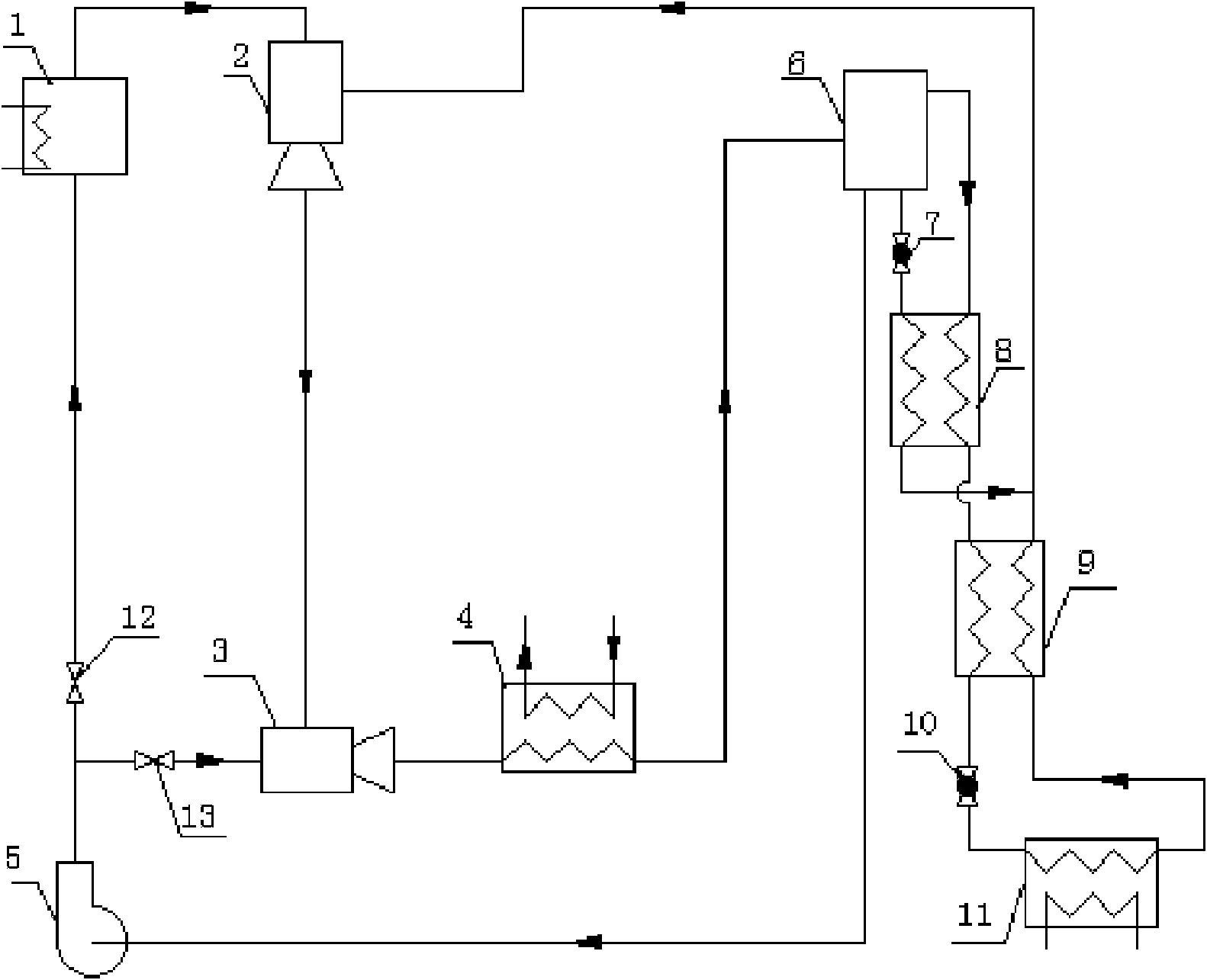
[0017] exist figure 1 Among them, a self-cascading ejector low-temperature refrigeration cycle system, including a generator 1, a gas ejector 2, a working medium pump 5, a condenser 4, a gas-liquid separator 6, a condensation evaporator 8, and a third regenerator 9 and the evaporator 11, the liquid mixed refrigerant in the generator 1 is heated and vaporized into a high-pressure superheated refrigerant vapor, which enters the gas injector 2 as working gas to inject the low-pressure side outlet of the condensing evaporator 8 and the third regenerator 9 The low-pressure mixed refrigerant steam at the outlet of the low-pressure side, the injected low-pressure mixed refrigerant steam is mixed and pressurized by the gas injector 2, and the gas at the outlet of the gas injector 2 is a superheated refrigerant mixed steam at an intermediate pressure state, and the working medium pump The supercooled liquid at outlet 5 passes through the condensing injector 3 and injects the superheate...

Embodiment 2

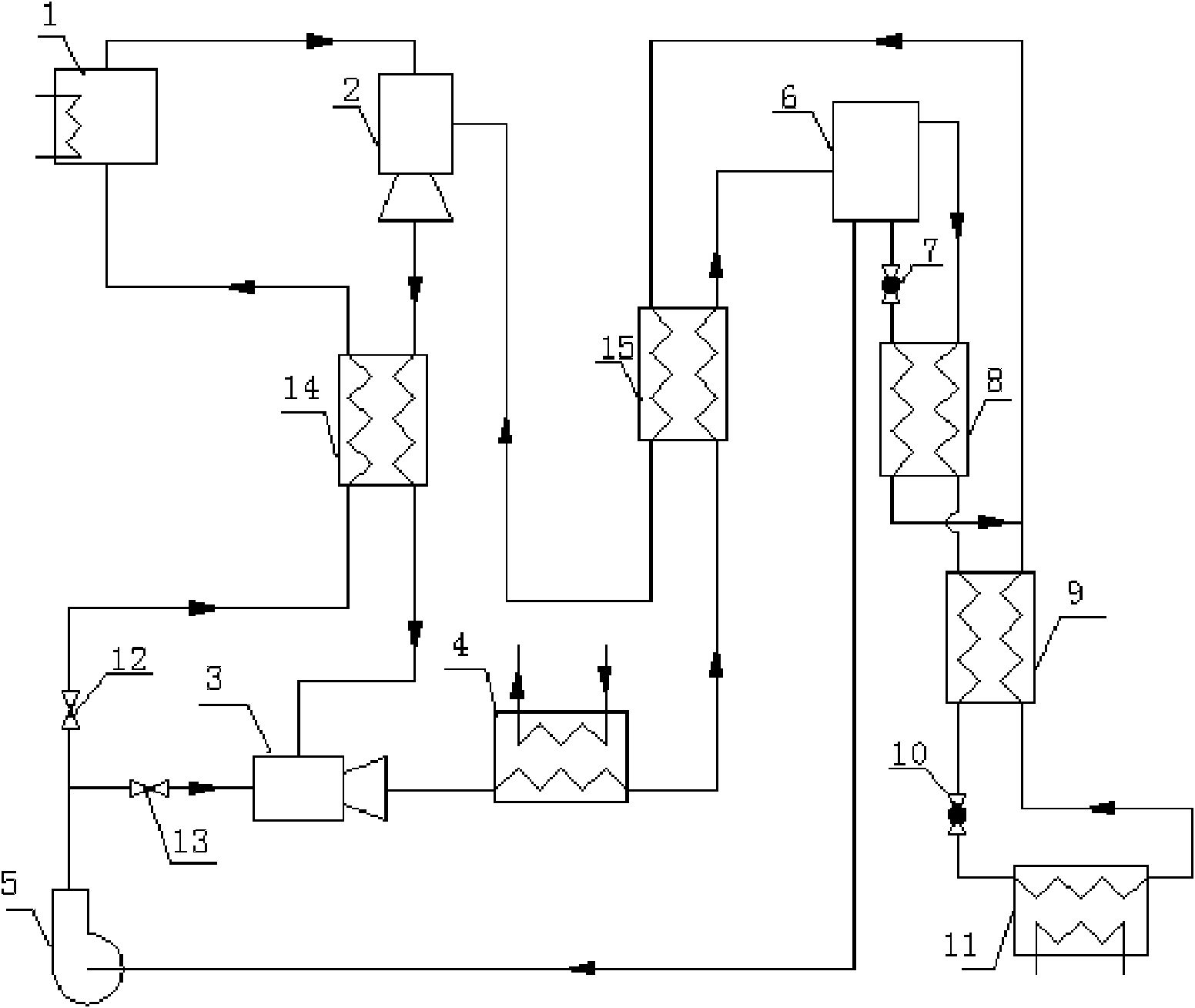
[0019] exist figure 2 In the generator 1, the liquid mixed refrigerant in the generator 1 is heated and vaporized into a high-pressure superheated refrigerant vapor, which enters the gas injector 2 as a working gas to inject the low-pressure refrigerant from the second regenerator 15, and is mixed by the gas injector 2 Supercharging effect, the superheated refrigerant mixed steam in the intermediate pressure state from the outlet of the gas injector 2 enters the first regenerator 14 for heat exchange, and is injected into the condensing injector 3 by the supercooled liquid pressurized by the working medium pump 5 Internal condensation and further pressurization, the high-pressure gas-liquid two-phase mixture refrigerant coming out of the outlet of the condensing injector 3 enters the condenser 4, and part of the gas-liquid two-phase mixture refrigerant is condensed, and passes through the second regenerator 15 After heat exchange, the gas-liquid two-phase mixed refrigerant en...


PUM


Abstract

The invention discloses an auto-cascade injection low-temperature refrigeration circulating device, which comprises a generator, an air injector, a working medium pump, a condenser, a liquid-vapor separator, an evaporator unit and a condensing injector. An inlet of the condenser is connected with an outlet of the condensing injector. The outlet of the condensing injector is connected with an inlet of the liquid-vapor separator. The liquid-vapor separator is provided with two liquid outlets, wherein one outlet is connected to an inlet of the working medium pump. An outlet of the working medium pump is divided into two paths, wherein one path is connected to an inlet of the condensing injector, while the other path is connected to an inlet of the generator. An outlet of the generator is connected with an inlet of the air injector. An outlet of the air injector is connected with an injection inlet of the condensing injector. The other liquid outlet of the liquid-vapor separator is connected with an inlet of the evaporator unit. A reflux opening of the evaporator unit is connected with an injection inlet of the air injector. An air outlet of the liquid-vapor separator is connected with another inlet of the evaporator unit. The auto-cascade injection low-temperature refrigeration circulating device increases the working pressure of the condenser through the condensing injector and can realize the low-temperature deep refrigeration temperature of less than 30 DEG C below zero.

Description

technical field [0001] The invention relates to a self-cascading jet low-temperature refrigeration cycle system, in particular to a self-cascade jet low-temperature refrigeration cycle system in which a condensing ejector realizes pressurization, and belongs to the technical field of low-temperature refrigeration. Background technique [0002] Jet refrigeration is a refrigeration method driven by low-grade energy, which can effectively utilize renewable energy such as solar energy and geothermal energy, as well as industrial waste heat and waste heat; the refrigerant used in jet refrigeration is mainly water, hydrocarbon natural working fluid or Hydrofluorocarbon refrigerants can avoid the use of ozone-depleting CFCs or HCFCs refrigerants. Traditional ejection refrigeration was widely used in large-scale building air-conditioning systems in the early 1930s, and was gradually replaced by mechanical compression refrigeration. At present, it is used in places where renewable en...

Claims


Application Information

Patent Timeline
IPC IPC(8): F25B19/02C09K5/04F25B41/04
Inventor 王林马爱华崔晓龙谈莹莹周西文任秀宏王雨
Owner HENAN UNIV OF SCI & TECH
Why Eureka
Try Eureka