Fiber grating, optical label coding method, use of optical label

A technology of fiber grating and coding method, applied in the field of optical multicast, to achieve the effect of simplifying the structure and improving the information capacity

Inactive Publication Date: 2009-12-16
TSINGHUA UNIV
View PDF0 Cites 2 Cited by
  • Summary
  • Abstract
  • Description
  • Claims
  • Application Information

AI Technical Summary

Problems solved by technology

However, so far, there is no solution that can simultaneously support large-scale multicast and only require a very simple node structure
Therefore, there are still problems in the practicality of the traditional optical multicast based on optical code labels.

Method used


Image

  • Fiber grating, optical label coding method, use of optical label
  • Fiber grating, optical label coding method, use of optical label
  • Fiber grating, optical label coding method, use of optical label

Examples


Embodiment 1

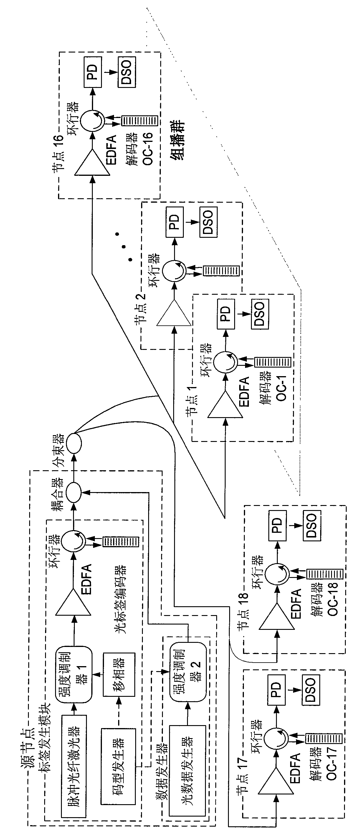
[0035] Such as figure 2 As shown, the optical multicast network of this embodiment is composed of one source node and 18 destination nodes, wherein nodes 1-16 form a multicast group. The source node is composed of a tag generation module and a data generation module. In the tag generation module, firstly, a 2ps pulsed fiber laser generates a short pulse sequence with a repetition rate of 10GHz, and the pattern generator generates an electrical pulse sequence of 311.25Mb / s, which is phase-shifted by a microwave phase shifter and then output to control the intensity modulator 1. After the 10GHz short pulse sequence passes through the intensity modulator 1, the repetition frequency is reduced to 311.25MHz, which is the data packet rate. The pulse sequence is encoded after passing through EDFA (Erbium-doped Optical Fiber Amplifier), circulator and optical label encoder, and the generated two-dimensional coded optical label is used to mark the multicast group.

[0036] In the da...


PUM


Abstract

The invention relates to a fiber grating, an optical label coding method and use of an optical label. The fiber grating is a fiber bragg grating on which multi-sampling two-dimension coding information on respective sampling of a plurality of cascade code words in the same chip period is inscribed. The optical label coding method obtains a coded optical label by writing the compiled multi-sampling two-dimension coding information into the fiber bragg grating and allowing a signal pulse to pass through the fiber bragg grating. The fiber grating and the optical label coding method can effectively avoid repeatedly updating a multicast router forwarding table and introducing a quick adjustable decoder in an optical multicast network to greatly simplify a network node structure, improves the information capacity of a single coder and can support large-scale all-optical multicast.

Description

technical field [0001] The invention relates to the field of optical multicast technology, in particular to an optical fiber grating, an optical label encoding method and an application thereof. Background technique [0002] Recently, it has become one of the promising technologies in all-optical multicast to apply the label based on optical orthogonal code (abbreviated as optical code label) to the optical multicast network based on packet switching. In all-optical multicast based on optical code tags, the complexity of nodes and the scalability of the network are the two most critical issues. However, so far, there is no scheme that can simultaneously support large-scale multicast and only need a very simple node structure. Therefore, the traditional optical multicast based on optical code labels still has problems in terms of practicability. Contents of the invention [0003] In order to realize a large-scale all-optical multicast optical multicast network under the p...

Claims


Application Information

Patent Timeline
Patent Type & Authority Applications(China)
IPC IPC(8): G02B6/02H04L12/56H04L12/18H04L45/50
Inventor 辛明陈明华陈宏伟尹飞飞谢世钟
Owner TSINGHUA UNIV
Why Eureka
Try Eureka