Equipment for preparing metal nano powder by spiral wire feed counter-current electrical explosion method
A metal nano-powder, counter-current technology, which is applied in the field of metal nano-powder production equipment of the spiral wire feeding counter-current electric explosion method, can solve the problems of imperfect technology and equipment, low energy utilization rate, low output rate, etc., and achieve The effect of high utilization rate of raw materials and energy, easy operation and high output
- Summary
- Abstract
- Description
- Claims
- Application Information
AI Technical Summary
Problems solved by technology
Method used
Image

Examples
Embodiment Construction
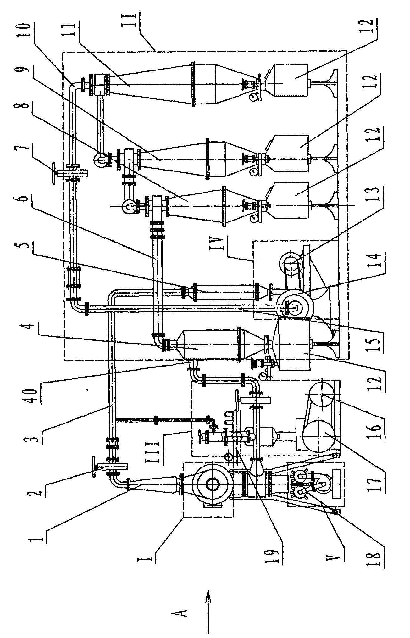
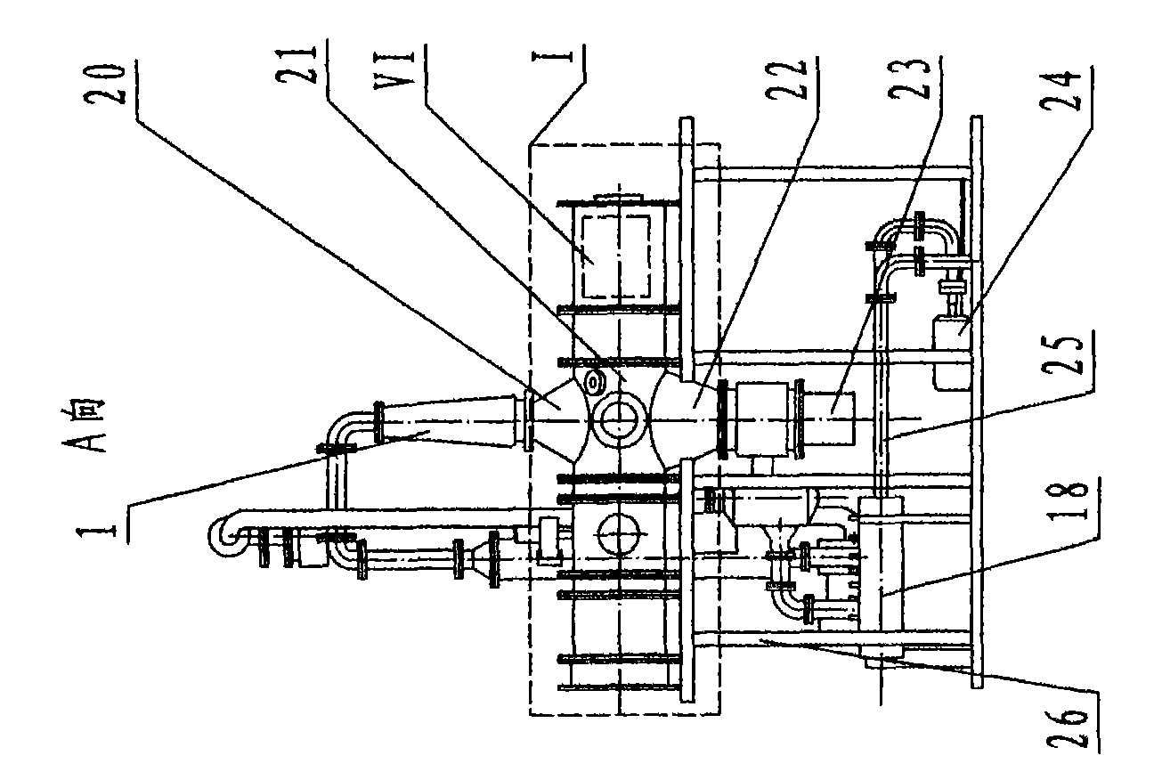
[0021] as attached figure 1 , 2 As shown, the equipment includes a host device I, a collection device II, a vacuum device III, an air delivery device IV, a water cooling device V, and a wire feeding mechanism VI. The host device I is arranged on the support 26, and is connected in series with the first collection bin 4, the second collection bin 8, the third collection bin 9, the fourth collection bin 11, and the high-pressure vacuum blower 14 through pipelines; the collection device II includes the first Collection bin 4, the second collection bin 8, the third collection bin 9, the fourth collection bin 11, packing box 12; vacuum device III includes motor 16, vacuum pump 17, vacuum table seat 19; air delivery device IV includes motor 13, high pressure Vacuum blower 14. The air inlet of the high-pressure vacuum blower 14 is connected through the air outlet 10 of the fourth collection bin 11 through the pipeline 15 through the gate valve 7, and the air outlet passes through t...
PUM
 Abstract
Description
Claims
Application Information
 - R&D
- Intellectual Property
- Life Sciences
- Materials
- Tech Scout
- Unparalleled Data Quality
- Higher Quality Content
- 60% Fewer Hallucinations
Browse by: Latest US Patents, China's latest patents, Technical Efficacy Thesaurus, Application Domain, Technology Topic, Popular Technical Reports.
© 2025 PatSnap. All rights reserved.Legal|Privacy policy|Modern Slavery Act Transparency Statement|Sitemap|About US| Contact US: help@patsnap.com