
Optical fiber vibration sensing head and manufacturing method thereof

A fiber optic vibration and sensing head technology, applied in the physical field, can solve problems such as complex assembly, difficult wavelength demodulation, and narrow frequency response range of optical detection vibration sensors, and achieve good consistency, expanded operating frequency range, and low cost. Effect

Inactive Publication Date: 2012-07-11
上海前所光电科技有限公司
View PDF4 Cites 1 Cited by
  • Summary
  • Abstract
  • Description
  • Claims
  • Application Information

AI Technical Summary

Problems solved by technology

[0010] The object of the present invention is to provide an optical fiber vibration sensing head, which needs to solve the problem that in the prior art, the electrical detection vibration sensor is susceptible to electromagnetic interference, the light detection vibration sensor has a narrow frequency response range, and the wavelength resolution Difficult adjustment and complex assembly technical issues

Method used


Image

  • Optical fiber vibration sensing head and manufacturing method thereof
  • Optical fiber vibration sensing head and manufacturing method thereof
  • Optical fiber vibration sensing head and manufacturing method thereof

Examples


Embodiment Construction

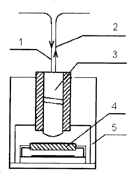
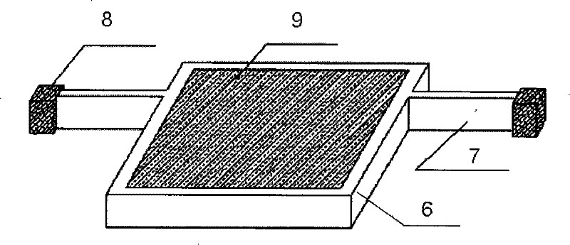
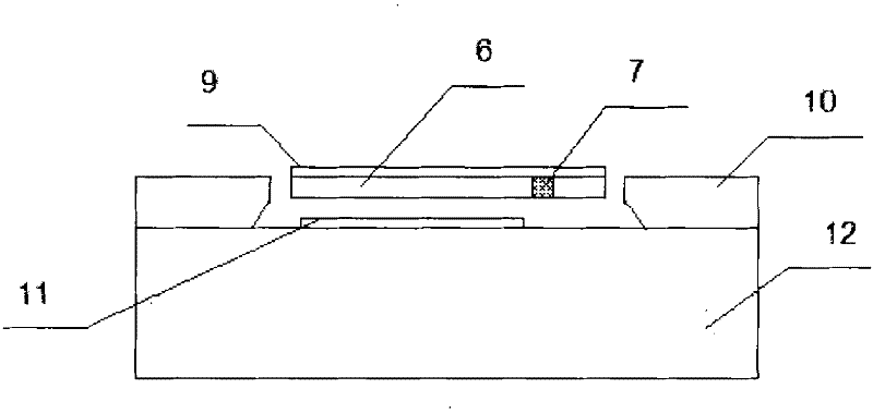
[0030] Such as figure 1 , figure 2 and image 3 As shown, the optical fiber vibration sensing head of the present invention is composed of a vibration sensitive chip 4, a double fiber collimator 3 and a package housing 5, and an input optical fiber 1 and an input fiber 1 are arranged in the described double fiber collimator 3 An output optical fiber 2, wherein the dual-fiber collimator 3 is fixedly arranged on the upper part of the package housing 5, and a cavity is provided in the package housing 5 below the dual-fiber collimator 3, and the vibration-sensitive chip 4 is arranged in the cavity, and the vibration-sensitive chip 4 is composed of a low-light reflector 6, a silicon support frame 10 and a substrate glass sheet 12, and the silicon support frame 10 is bonded to the substrate glass sheet 12 Together, the low-light reflector 6 is arranged in the silicon support frame 10, a damping air cavity is arranged between the low-light reflector 6 and the substrate glass sheet...


PUM

PropertyMeasurementUnit
thicknessaaaaaaaaaa
thicknessaaaaaaaaaa

Abstract

The invention discloses an optical fiber vibration sensing head, which consists of a vibration sensitive chip, a dual fiber collimator and an encapsulation shell, wherein the inside of the encapsulation shell under the dual fiber collimator is provided with a cavity, the vibration sensitive chip is arranged in the cavity and consists of micro light reflector, a silicon supporting frame and a substrate glass sheet; the silicon supporting frame is bonded with the substrate glass sheet; the micro light reflector is arranged in the silicon supporting frame; a damping air cavity is reserved between the micro light reflector and the substrate glass sheet; two sides of the micro light reflector is symmetrically provided with torsion shafts; and one end of each of the torsion shaft is connected with the silicon supporting frame. An MEMS process is used to integrate a MEMS vibration sensitive chip. Based on an asymmetric torsion micro light reflector structure, the MEMS vibration sensitive chip can be manufactured in batch. The torsion shafts are used as elastic elements, and the micro light reflector is used as a sensitive mass block to reflect vibration acceleration. The damping air cavity is used for controlling the damping characteristic of torsion. The invention has the advantages of batch production, low cost and high consistency.

Description

Technical field: [0001] The invention relates to the field of physics, in particular to light transmission technology, in particular to an optical fiber vibration sensor head and a manufacturing method thereof. Background technique: [0002] The vibration signal measured by the vibration sensor can be characterized by vibration acceleration or vibration amplitude. Therefore, the detection of vibration signals has two schemes: vibration detection based on vibration acceleration and vibration detection based on vibration amplitude. Vibration detection based on vibration acceleration is the main one. detection scheme. Vibration detection devices based on vibration acceleration include electrical detection vibration sensors and photoelectric detection vibration sensors. [0003] The electric detection vibration sensor uses a vibration sensitive mechanism to perceive vibration acceleration, and the vibration sensitive mechanism is mainly composed of a sensitive mass block, an el...

Claims


Application Information

Patent Timeline
Patent Type & Authority Patents(China)
IPC IPC(8): G01H9/00G02B26/08G03F7/00
Inventor 吴亚明钟少龙
Owner 上海前所光电科技有限公司
Learn More