LTCC bandpass filter with harmonic suppression
A band-pass filter and harmonic suppression technology, applied in the field of electronics, can solve problems such as insufficient stop-band attenuation, and achieve the effects of compact structure, low mass production cost, and reduced volume
- Summary
- Abstract
- Description
- Claims
- Application Information
AI Technical Summary
Problems solved by technology
Method used
Image
Examples
Embodiment Construction
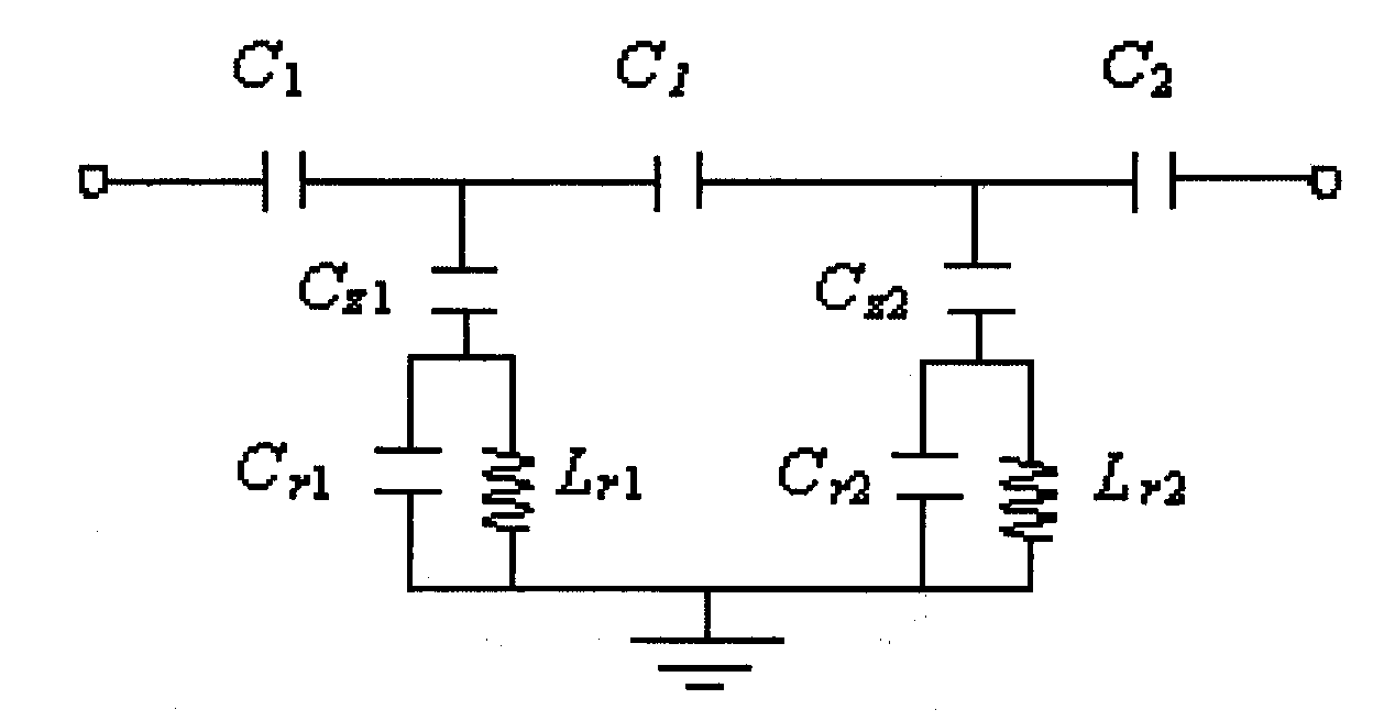
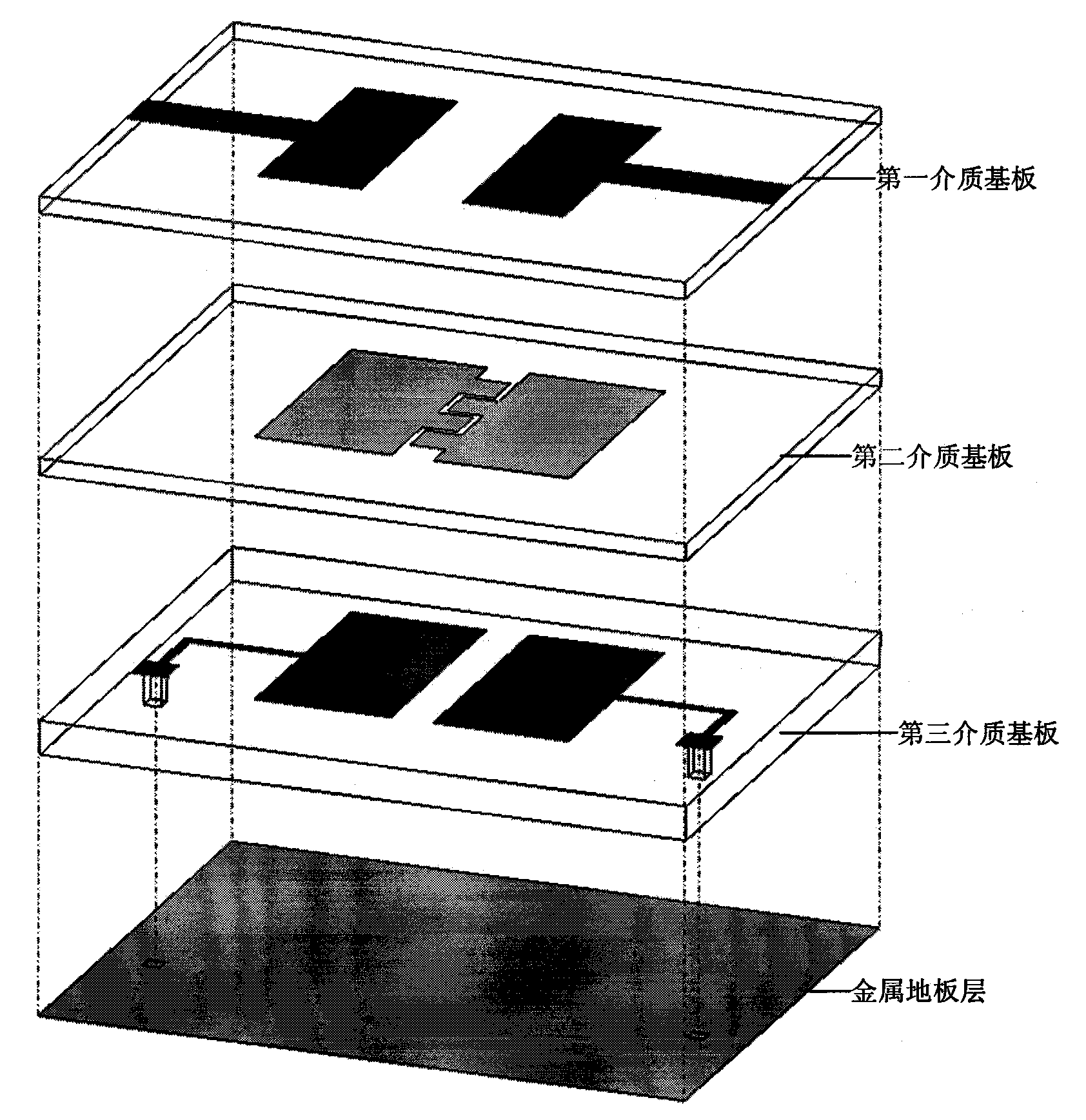
[0015] Such as figure 1 , 2 As shown, the structure of the LTCC harmonic suppression bandpass filter and its equivalent circuit of the specific embodiment of the present invention have been described in detail in the summary of the invention, so they will not be repeated here, and only the detailed parameters of each part are described as follows:
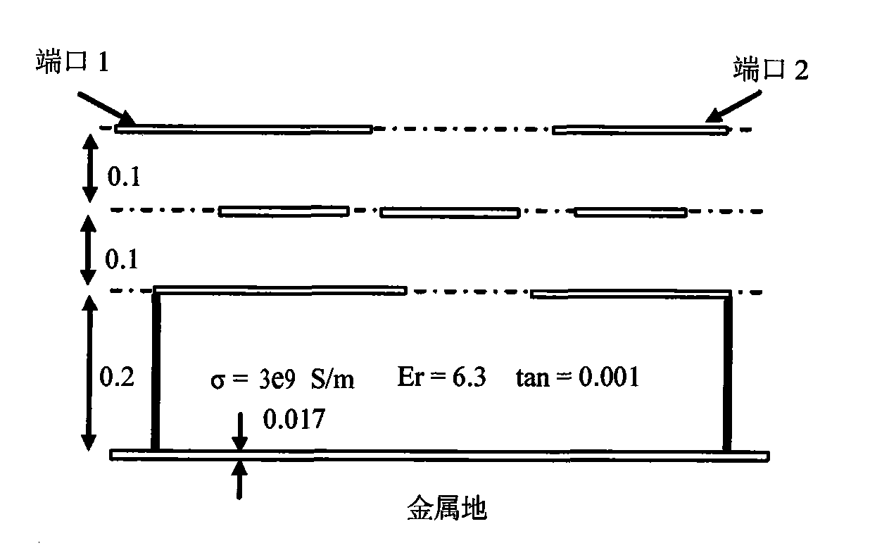
[0016] Such as image 3 Shown: The thickness of the first and second dielectric substrates is 0.1mm, the thickness of the third dielectric substrate is 0.2mm, and the thickness of the fourth conductor layer is 0.017mm; the metal used in the conductor layers is gold; the dielectric substrate material is Ferro A6M type LTCC ceramic material, its relative permittivity Er is 6.3, dielectric loss tangent tan is 0.001, conductivity σ is 3×10 9 S / m; the volume of the whole device is only 3.5mm×4mm×0.6mm.
[0017] Test results such as Figure 4 As shown, the bandpass filter works at 2.8-3.2G Hz, there is a transmission zero at the harm...
PUM
 Abstract
Description
Claims
Application Information
 - R&D
- Intellectual Property
- Life Sciences
- Materials
- Tech Scout
- Unparalleled Data Quality
- Higher Quality Content
- 60% Fewer Hallucinations
Browse by: Latest US Patents, China's latest patents, Technical Efficacy Thesaurus, Application Domain, Technology Topic, Popular Technical Reports.
© 2025 PatSnap. All rights reserved.Legal|Privacy policy|Modern Slavery Act Transparency Statement|Sitemap|About US| Contact US: help@patsnap.com


