
Electron beam evaporation source device

An electron beam evaporation and source device technology, applied in vacuum evaporation plating, ion implantation plating, metal material coating process, etc., can solve the problems of complex equipment structure, high price and high cost, and achieve cost reduction and cost reduction , reliable and easily adjustable effect

Active Publication Date: 2011-04-27
丁海峰
View PDF0 Cites 0 Cited by
  • Summary
  • Abstract
  • Description
  • Claims
  • Application Information

AI Technical Summary

Problems solved by technology

[0004] At present, only a few companies can produce the ultra-high vacuum electron beam evaporation source with the function of molecular beam epitaxy, but its price is relatively expensive, and the structure of the whole equipment is relatively complicated, and the preparation requirements are extremely fine, resulting in extremely high cost. Hundreds of thousands of euros

Method used


Image

  • Electron beam evaporation source device
  • Electron beam evaporation source device
  • Electron beam evaporation source device

Examples


Embodiment

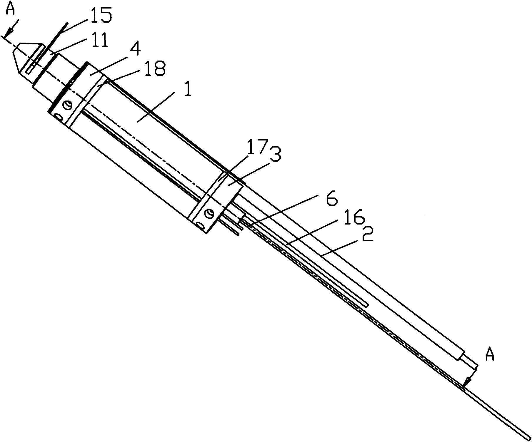
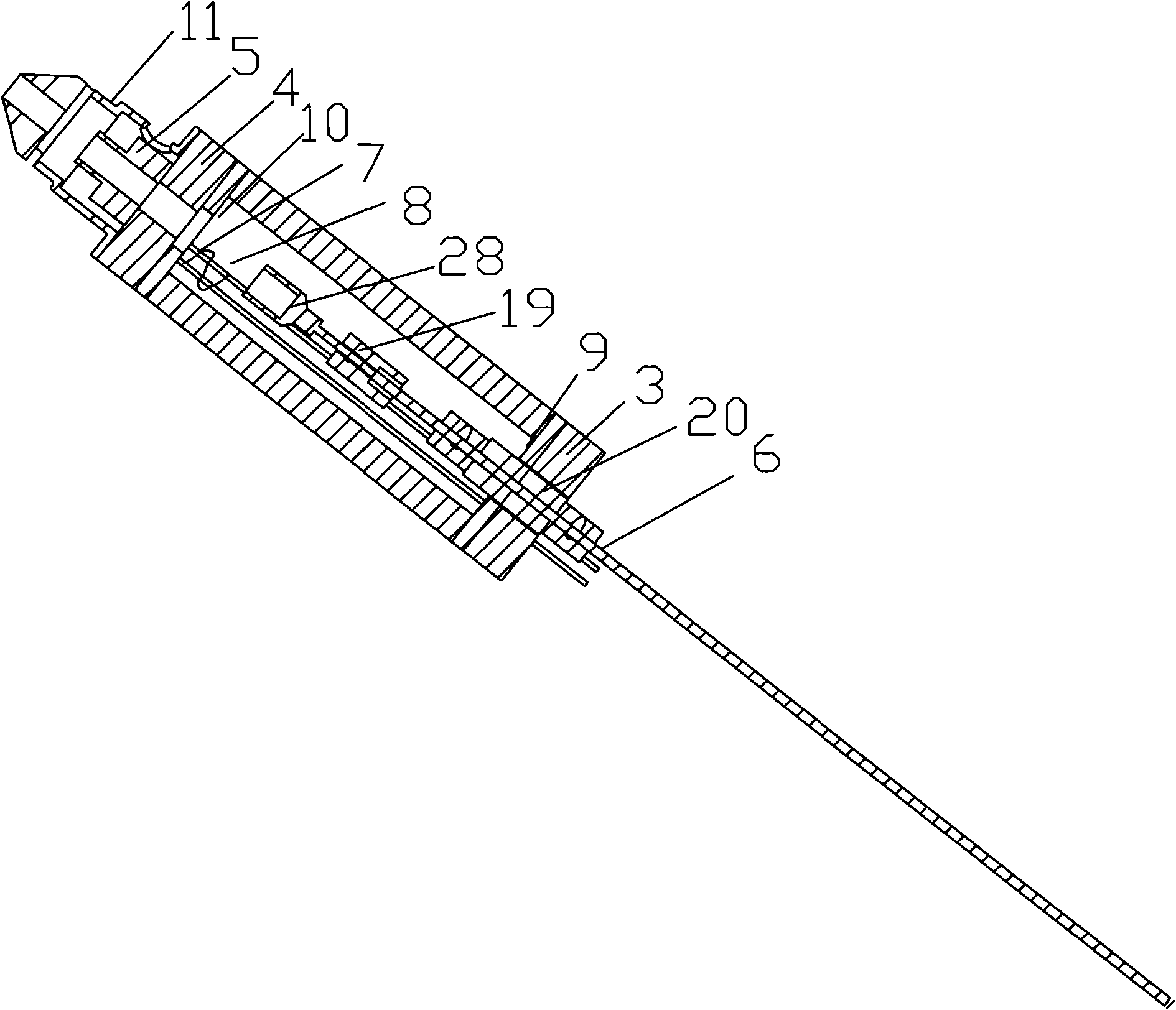
[0046] More specifically, when the present invention is implemented, if the electron beam evaporation source device is connected to the multi-port flange for ultra-high vacuum, an ultra-high vacuum multi-pin electronic wire connector is installed on the multi-port flange for feeding The high voltage of the material to be evaporated is connected to the ultra-high vacuum high-voltage wire connector, the cooling water inlet and outlet, that is, the connecting pipe, and the rotating device connected with the control rod 16 to control and close the baffle. The front end of the shell is fixed with a stainless steel collector shell with a middle hole and an ion beam collector. Two insulating ceramic covers are installed at both ends of the cylindrical shell, and the central part of the insulating ceramic covers at both ends is provided with multiple perforations. , from the perforation through the metal rod providing high voltage and the molybdenum rod wire connected to the heating fi...


PUM

PropertyMeasurementUnit
diameteraaaaaaaaaa
lengthaaaaaaaaaa
lengthaaaaaaaaaa

Abstract

The invention discloses an electron beam evaporation source device which comprises a shell with an inner cavity, a condenser tube, a first insulating part, a second insulating part, an ion beam collector, an evaporating stick for fixing evaporation materials, two conductors and lamp filament. The shell is provided with a first opening and a second opening; the first opening and the second openingare respectively and hermetically connected with the first insulating part and the second insulating part; the ion beam collector is connected with the second insulating part; a collector casing is nested outside the ion beam collector; through holes by which ion beams are ejected are arranged on the second insulating part, the ion beam collector and the collector casing; the evaporating stick and one side of each of two conductors are positioned in the cavity of the shell, and the other side of each of the two conductors extends out of the first insulating part; the lamp filament is connected with one end of each of the two conductors positioned in the cavity; and the condenser tube is tightly connected with the shell. The invention conforms to international standard technical indexes, simplifies the processing and assembling process and reduces the cost.

Description

technical field [0001] The invention relates to a thin film preparation device, in particular to an ultra-high vacuum electron beam evaporation source device with molecular beam epitaxy function in electron beam evaporation equipment. Background technique [0002] Thin film technology has been widely used in industry, especially in the fields of electronic materials, magnetic materials and components industry. Therefore, the methods of preparing thin films with various properties have also been developed by leaps and bounds in recent decades. So far, the preparation methods of thin films have been developed: physical vapor deposition (Physical Vapor Deposition, PVD), including vacuum evaporation coating method, sputtering coating method, ion coating method and molecular beam epitaxy growth, etc.; chemical vapor deposition (Chemical Vapor Deposition) Vapor Deposition, CVD); Oxidation method; Electroplating method; Coating, precipitation method, etc. The most commonly used m...

Claims


Application Information

Patent Timeline
Patent Type & Authority Patents(China)
IPC IPC(8): C23C14/30
Inventor 丁海峰
Owner 丁海峰
Learn More