Construction machine for casting underdrain on site by cement

A technology of construction equipment and cement, which is applied to the field of cast-in-place construction equipment of farmland irrigation and drainage culverts, can solve the problems of insecurity, easy damage, low efficiency and the like

Inactive Publication Date: 2010-01-06
孙加林
View PDF0 Cites 3 Cited by
  • Summary
  • Abstract
  • Description
  • Claims
  • Application Information

AI Technical Summary

Problems solved by technology

It is more convenient to pour the lower half pipe by this method, and it can pour a long section continuously at one time, but it is not good for the upper half pipe. The wooden formwork must be erected in the lower half pipe before pouring the upper half pipe, and only 20 meters can be poured at a time. To 40 meters long, it takes more than two hours to erect the wooden formwork once, and it takes another 6 to 8 hours to wait for the cement to solidify after pouring, and it takes another hour or two to drill into the culvert to remove the wooden formwork. It takes 8 to 10 hours to pour a section, which is not only inefficient, but also consumes a lot of wood, and the wooden formwork is easily damaged after being disassembled many times. At the same time, it is not safe for people to drill in and remove the wooden formwork, especially for branch canals with small inner diameters. Had to climb in, lie down and remove the wooden formwork

Method used


Image

  • Construction machine for casting underdrain on site by cement
  • Construction machine for casting underdrain on site by cement
  • Construction machine for casting underdrain on site by cement

Examples


Embodiment 1

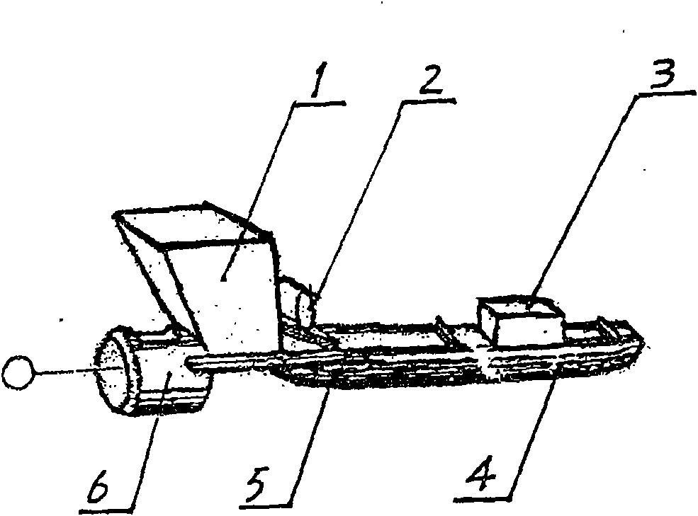
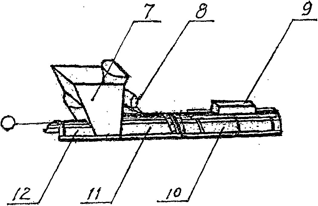
[0011] figure 1 Shown is the schematic diagram of the lower half-pipe forming slipform. When pouring the lower half-pipe, the excavated soil canal wall must be smoothed and the residual soil in the groove must be removed, and then the lower half-pipe forming slipform shall be erected in the soil groove Above, the gap between the sliding form and the wall of the soil tank should be equal to the wall thickness of the cement pipe. Put the cement concrete into the lower half pipe hopper 1, and the front traction mechanism pulls the lower half pipe forming sliding form forward through the guide section 6, and the cement concrete continues to move forward. To fill the cavity of the soil canal, there is a vibrator 2 on the upper side of the lower half-pipe vibration forming section 5 to vibrate the cement compactly, and there is a counterweight 3 on the lower half-pipe smoothing section 4, and their function is to compact the cement. The cement is troweled, so that the sliding form k...

Embodiment 2

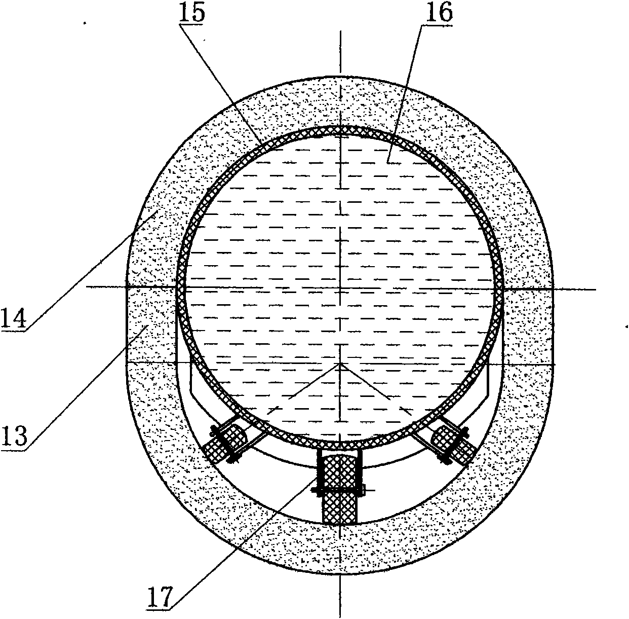
[0013] Such as image 3 As shown, after the lower half pipe is poured and solidified, several small sports cars 17 are laid in the lower half pipe. The length of each small sports car is 2 meters. The number of small sports cars is determined according to the length of the water bag. The small sports cars are connected by wire ropes. , Water bladder 15 is laid on the small sports car. When the pressure water 16 was full of the water bag 15, the pouring construction of the upper half pipe could be carried out. In order to prevent the cement from sticking to the water bag 15, a layer of plastic film was spread on the surface of the upper half of the water bag 15. Set up the upper half pipe forming slide form on the lower half pipe 13 and the water bag 15, the gap between the upper half pipe sliding form inner cavity and the water bag 15 should be equal to the wall thickness of the upper half pipe 14 of cement, and add the upper half pipe feeding hopper 7 For cement concrete, th...


PUM


Abstract

The invention relates to a construction machine for casting underdrain on site by cement, mainly comprising an upper half pipe molding slip form, a lower half pipe molding slip form, water sacs, a small trolley, and the like. The construction machine is mainly used for casting the underdrain used for irrigating or draining farmland on site by cement. The construction machine adopts the technical scheme that the water sacs are inlaid on the small trolley, are filled with pressure water and are used as cast-in-situ inner forms so as to replace the wood plate stumpage formwork of the prior art, thereby saving the time of erecting or disassembling the wood former and greatly shortening the construction period. The invention disassemblies the wood formwork without requiring a worker to plunge into the underdrain, thereby eliminating unsafe factors and reducing the labor intensity of workers; and the inner face of the underdrain cast by the construction machine is smooth and continuous without uneveness, thereby improving the quality of the underdrain, saving a great amount of wood and reducing the construction cost.

Description

Technical field [0001] The invention belongs to an underground channel construction machine, in particular to a cast-in-place construction machine tool for a farmland irrigation and drainage culvert. Background technique [0002] With the aggravation of the shortage of water resources in our country, the contradiction of irrigation water for farmland is becoming more and more serious. The 17th National Congress of the Communist Party of China proposed to "accelerate the construction of a water-saving society". In particular, the irrigation of the farmland has been changed from the soil canal to the U-shaped open channel cast in place by cement, and then improved to an underground culvert. This improvement has greatly reduced the losses caused by the seepage and evaporation of the earth canal, but it is a very huge project for the construction of the underground irrigation canal with a large area and a large amount. First of all, it is impossible to lay farmland culverts wit...

Claims


Application Information

Patent Timeline
IPC IPC(8): E02B13/00E02B5/02E02D15/00
Inventor 蒋宝华孙加林秦建国
Owner 孙加林
Why Eureka
Try Eureka