Method for removing underway seeper of superficial layer of filtration and infiltration well

A technology of road water accumulation and infiltration well, which is applied in the direction of removing sewage, drainage structures, chemical instruments and methods, etc., can solve the problems of easy aging of waterproof materials, easy water accumulation in drainage, water accumulation in channels, etc., so as to achieve a good social economy and environment. Benefit, easy promotion and application, the effect of eliminating pollutants

Inactive Publication Date: 2010-01-06
CHANGSHA UNIVERSITY OF SCIENCE AND TECHNOLOGY
View PDF0 Cites 8 Cited by
  • Summary
  • Abstract
  • Description
  • Claims
  • Application Information

AI Technical Summary

Problems solved by technology

Among them, the main defect of the canopy drainage is that the waterproof material used is easy to age, the cost is high, and the replacement and maintenance costs of the canopy are relatively large.
Moreover, this method is likely to cause water accumulation in the passage; the main defect of the drainage of the evaporation pond is that it occupies a large area, and the cost is relatively high, and it cannot meet the drainage requirements during heavy rains, and it is easy to cause water accumulation in the road below; and seepage pits or Although the seepage ditch drainage method has a certain interception and percolation purification effect on the road surface runoff, the drainage effect is not good, especially in the case of heavy rain, the drainage is slow and easy to accumulate water, which affects the normal passage of the underpass road and may also affect the surrounding environment. and groundwater pollution

Method used


Image

  • Method for removing underway seeper of superficial layer of filtration and infiltration well

Examples


Embodiment 1

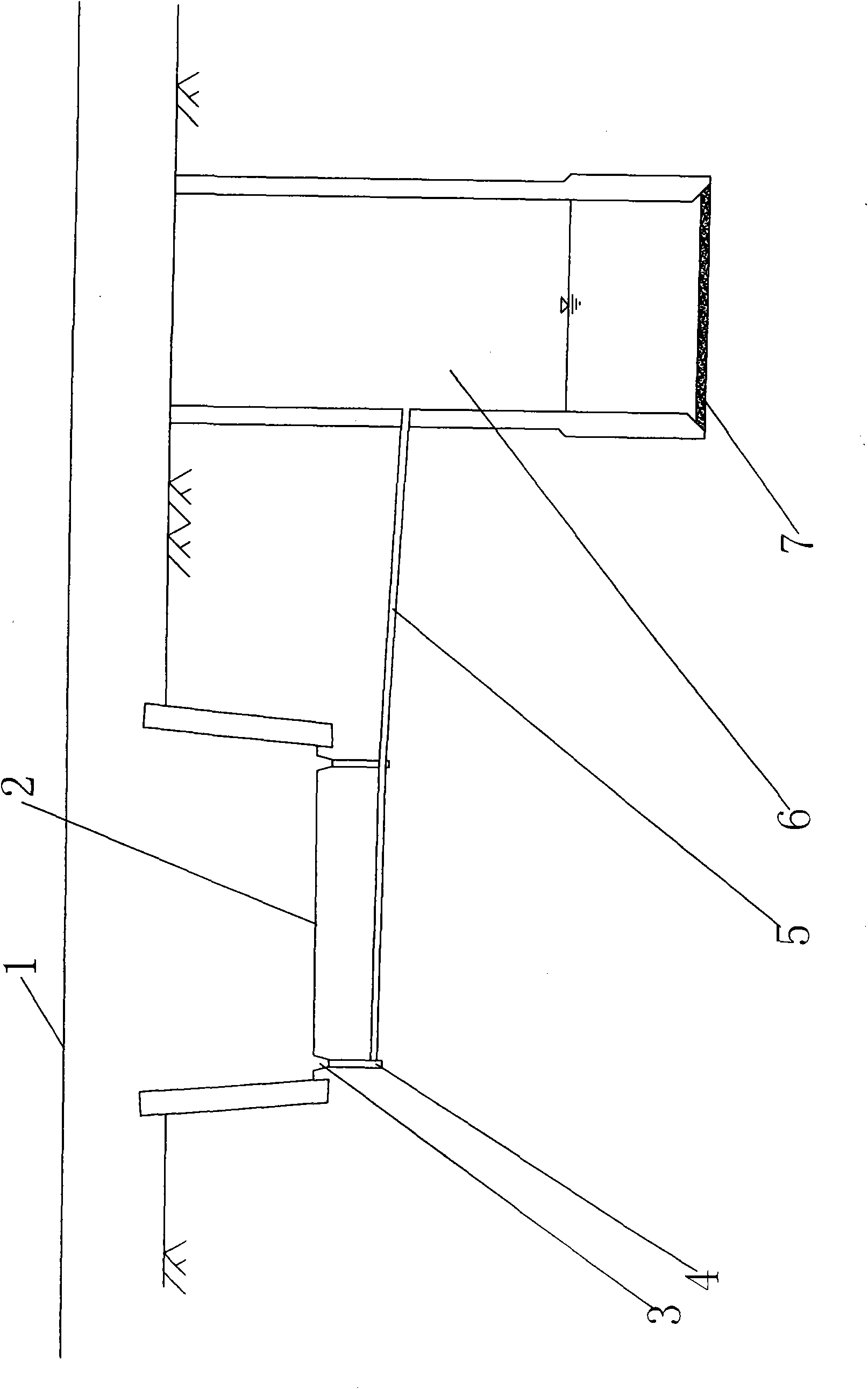
[0015] Example 1, see figure 1 In this embodiment, the water collection well 4 is located under the side ditch 3 on both sides of the intersection between the main road line 1 and the underpassed road 2 . The infiltration well 6 adopts reinforced concrete construction, and is located in the permeable soil layer above the groundwater level at the side of the water collection well 4. The grid 7 at the bottom of the infiltration well 6 adopts a vermiculite grid with good filtering and infiltration functions, and the commercially available 0.5m thick vermiculite grid is filled with vermiculite particles in the grid. The water collection well 4 and the infiltration well 6 are connected by a reinforced concrete drainage pipe 5 with a pipe diameter of ¢70cm.

Embodiment 2

[0016] In Embodiment 2, the water collection well 4 is arranged under the dark ditch on both sides of the crossing road between the main road line 1 and the underpassing road 2 . The permeation well 6 adopts bellows construction, and is located in the permeable soil layer above the groundwater level at the side of the water collection well 4. The bottom of the infiltration well 6, that is, the grid 7, also uses a commercially available 0.5m thick vermiculite grid. The drainage pipe 5 connecting the water collection well 4 and the infiltration well 6 also adopts the reinforced concrete material with a pipe diameter of ¢70cm. In order to further prevent too much floating matter from entering the infiltration well, one or more layers of wire mesh can also be added at the entrance of the drainage pipe 5 to carry out preliminary filtration of rainwater.

[0017] This method of filtering the shallow layer of the permeation well of the present invention to remove the accumulated wat...


PUM


Abstract

The invention provides a method for removing underway seeper of a superficial layer of a filtration and infiltration well. The method comprises the following steps that: sump wells (4) are arranged under two side drains (3) of a cross road between a road mainline (1) and a crossed road (2) respectively; an infiltration well (6) is arranged above the side underground water level of the sump well (4); the pool bottom of the infiltration well (6) is provided with vermiculite grating (7) with excellent functions of filtration and infiltration; the sump well (4) and the infiltration well (6) are connected by a drainpipe (5); and pollutants are removed by the vermiculite grating (7), and purified water is drained. The method has reasonable design and simple arrangement, can infiltrate surface runoff to underground permeable ground of the superficial layer, can quickly remove the pollutants, has the characteristics of easy popularization in road construction, good effect, fast effect, environmental protection and economy, and can obtain good social, economic and environmental benefit.

Description

technical field [0001] The invention belongs to the technical field of highway engineering, and in particular relates to an underpassing road pond water removal method suitable for expressways after the embankment height has been reduced. Background technique [0002] In order to reduce the filling height of expressway embankment, and at the same time ensure that the ground rainwater collected by the underpassing road can be discharged in time, and the normal traffic of the road will not be affected under normal rainfall intensity, the commonly used drainage methods mainly include canopy drainage, Evaporation pond drainage and seepage pit or ditch drainage and other methods. Wherein the main defect of canopy drainage is that the waterproof material used is easy to age, the cost is high, and the replacement and maintenance costs of the canopy are relatively large. Moreover, this method is likely to cause water accumulation in the channel; the main defect of the drainage of t...

Claims


Application Information

Patent Timeline
Patent Type & Authority Applications(China)
IPC IPC(8): E03F1/00E03F5/04E03F5/14
Inventor 刘朝晖秦仁杰周科峰
Owner CHANGSHA UNIVERSITY OF SCIENCE AND TECHNOLOGY
Why Eureka
Try Eureka