Eureka AIR delivers breakthrough ideas for toughest innovation challenges, trusted by R&D personnel around the world.

Microwave plasma burner

a plasma burner and microwave technology, applied in plasma technology, welding apparatus, manufacturing tools, etc., can solve the problems of high operational cost, high electrical-power supplier, inefficient devices of induction torch and high-frequency capacitive torch, etc., and achieve the effect of protecting the publi

Inactive Publication Date: 2007-01-11
UHM HAN S
View PDF2 Cites 19 Cited by
  • Summary
  • Abstract
  • Description
  • Claims
  • Application Information

AI Technical Summary

Benefits of technology

[0016] It is therefore an important object of the present invention to generate a large-volume of plasma flames with high temperature from hydrocarbon fuel and swirl gas so that this plasma flame serves as a high temperature source in waste incineration facilities where hazardous materials like dioxins may not be formed because of controlled incineration temperature due to the high temperature source of the present invention.
[0018] Another object of the present invention is generation of a high-temperature large-volume plasma flame for quick elimination of poisonous gas in air sprayed by terrorists, thereby deterring terror actions and protecting the public against any terrorist attack.

Problems solved by technology

The DC arc torch is operated by the DC electric field between two electrodes, which must be replaced often due to their limited lifetime.
The DC arc torch is also operated at a high arc current in the range of 50-10,000 A, which requires an expensive high electrical-power supplier.
The induction torch and high-frequency capacitive torch are inefficient devices with typical thermal efficiency in the range of 40-50%.
These conventional torches have a small volume of plasma, have high operational cost and require many expensive additional systems for operation.
The microwave plasma torch provides high density and high temperature plasmas in inexpensive ways, but the plasma volume and temperature of the microwave plasma torch decrease drastically outside the discharge tube, thereby limiting its capability of bulk treatment of waste.

Method used


Image

  • Microwave plasma burner
  • Microwave plasma burner
  • Microwave plasma burner

Examples


example

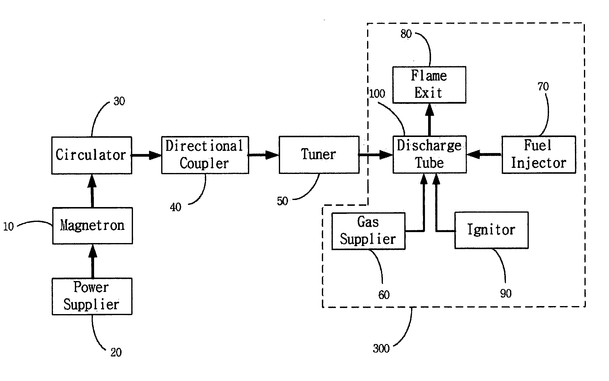
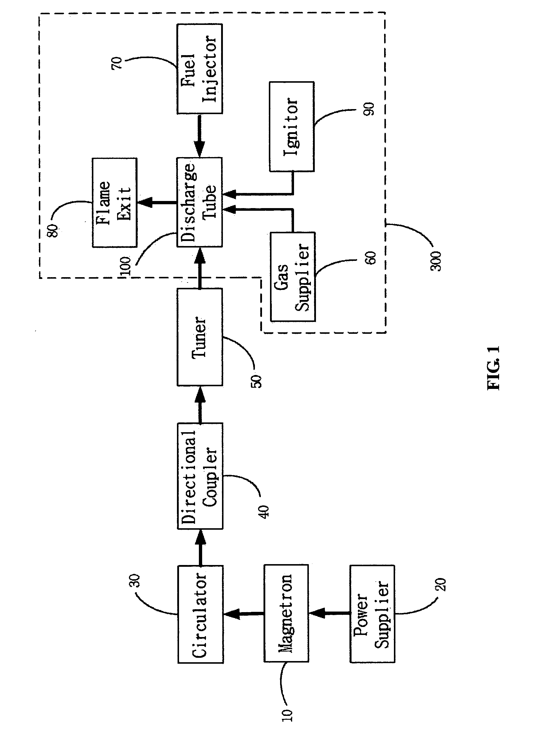
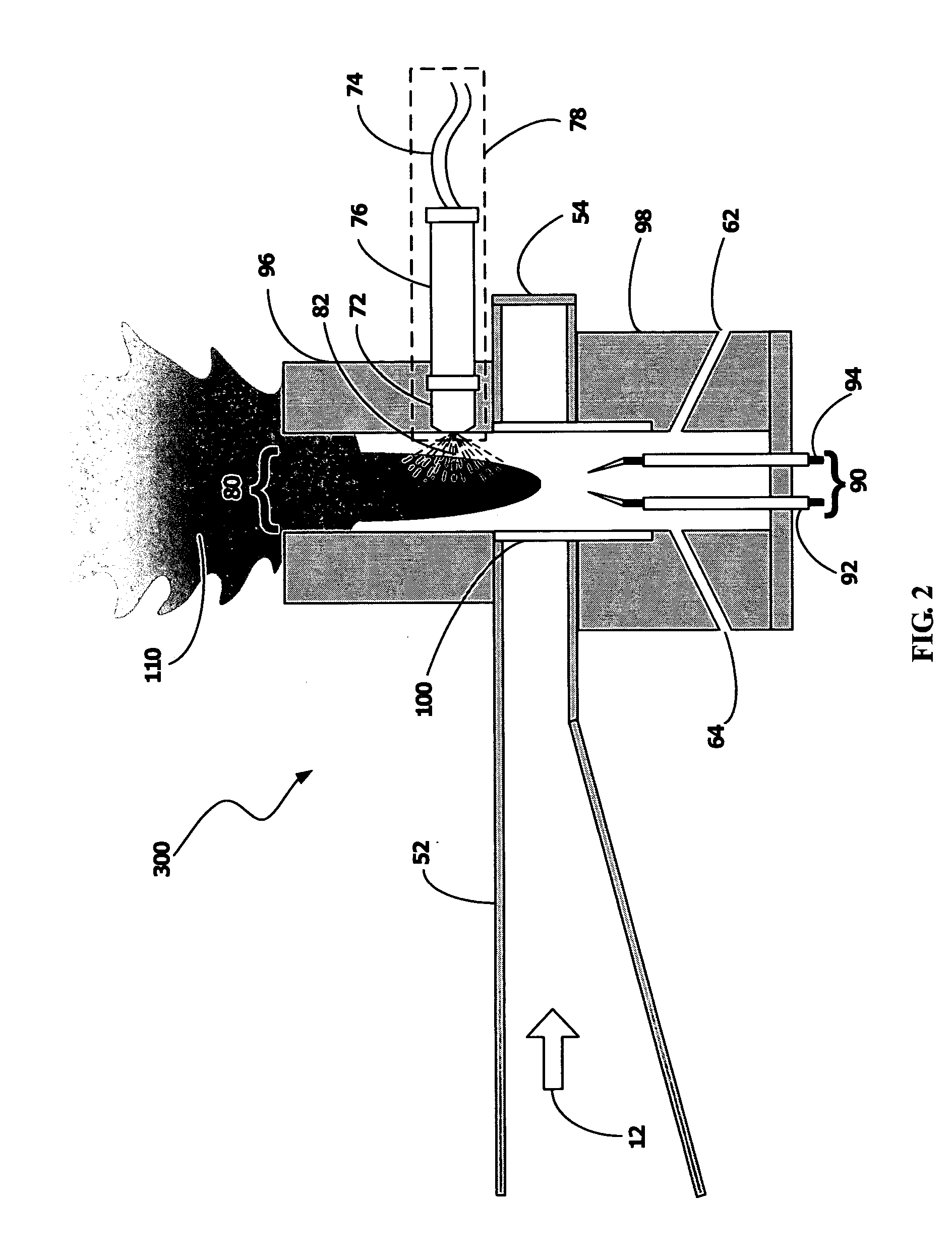
[0040] The microwaves 12 with 2.45 GHz and 1 kW power generated from the magnetron 10 enter the discharge tube 100 with its inner diameter of 27 mm. The air swirl gas of 50 liters per minute (lpm) from the gas supply 60 creates a vortex flow inside the discharge tube 100. Kerosene injected from the fuel injector system 78 in FIG. 2 into the discharge tube 100 is 1500 cc per hour. The length of the downstream housing 96 in FIG. 2 is about 10 cm. The plasma flame is shooting out through the flame exit 80 in FIG. 2. The plasma flame diameter and length from the flame exit 80 are about 10 cm and 40 cm, respectively. The flame temperature at the center of the flame exit measured by a thermo-coupler is about 1400 degree Celsius. 20 lpm oxygen gas is added to the swirl gas and it was observed that the plasma flame color changes from yellowish white to bluish white. The flame temperature at the flame exit with additional oxygen gas is measured to be 1700 degree Celsius.


PUM

PropertyMeasurementUnit
currentaaaaaaaaaa
inner diameteraaaaaaaaaa

Abstract

The present invention relates to an apparatus for generating flames and more particularly to the microwave plasma burner for generation of high-temperature plasma flame by injecting gaseous, liquid or solid-powder hydrocarbon-fuels into plasma generated by microwaves. The invention provides a compact and portable apparatus for generating plasma flame. The apparatus includes a magnetron, an electrical power supplier, a waveguide system, a microwave power monitering system, stub tuners, a discharge tube, a gas supply system, a plasma ignitor and a fuel supply system. The method and apparatus is described for generation of a large volume of high-temperature plasma by injecting gaseous, liquid or solid-powder hydrocarbon-fuels into the microwave plasma torch to decompose the hydrogen and carbon containing fuels, and to mix the resultant gaseous hydrogen and carbon compounds with air or oxygen gas, instantaneously generating a large volume of high-temperature flames.

Description

REFERENCE CITED [0001] U.S. Patent Documents 5,505,90904 / 1996Dummersdorf et al5,830,32811 / 1998Uhm6,620,394 B209 / 2003Uhm et al6,620,439 B210 / 2004Uhm et alFIELD OF THE INVENTION [0002] The present invention relates generally to the apparatus for generating flames, and particularly to the microwave plasma burner for generating a large volume of high-temperature plasma flames by injecting gaseous, liquid or solid-powder hydrocarbon-fuels into an atmospheric microwave plasma torch and by near perfect combustion of the fuels with air or oxygen gas through the high-temperature plasma torch. BACKGROUND OF THE INVENTION [0003] The plasma torch in general is a device of arc plasma column generated between two electrodes. There are several kind of plasma torch including DC arc torch, induction torch and high-frequency capacitive torch. The DC arc torch is operated by the DC electric field between two electrodes, which must be replaced often due to their limited lifetime. The DC arc torch is a...

Claims


Application Information

Patent Timeline
Patent Type & Authority Applications(United States)
IPC IPC(8): B23K9/00B23K9/02
CPCH05H1/30
Inventor UHM, HAN SUPHONG, YONG C.YI, WON JU
Owner UHM HAN S
Why Eureka
Eureka Blog
Learn More