Modularized energy storing device

A technology of energy storage devices and capacitor banks, which is applied in the direction of electric energy storage systems, electrical components, fixed capacitor parts, etc., can solve the problems of limited chemical reaction rate, life limit, battery capacity decline, etc., to increase the popularization of use performance, reduction in manufacturing cost, and increased convenience

Inactive Publication Date: 2010-01-13
LITE ON TECH CORP
View PDF0 Cites 1 Cited by
  • Summary
  • Abstract
  • Description
  • Claims
  • Application Information

AI Technical Summary

Problems solved by technology

Although the general capacitor is relatively simple in manufacturing process, it can only be used as short-term energy storage because of its small storage capacity.
The battery mainly uses chemical energy to store energy, so its energy storage density is significantly better than that of general capacitors, and it can be applied to various power supply devices, but its disadvantage is that the instantaneous power output it can generate will be affected. Limited to the chemical reaction rate, it cannot charge and discharge quickly or perform high power output, and the number of charge and discharge is limited, and it is easy to cause various problems when excessive charge and discharge
For example: Although the batteries currently used are advertised as reusable, they still have a life limit
In the case of repeated charging and discharging or long-term non-use, the capacity of the battery will decrease and it will be easily damaged. The reason is that the battery uses chemical energy to convert into electrical energy. When the activity of the original compound is used up or nearly used up, no new chemical reaction can be carried out, which leads to the aging of the battery and the end of its life
[0006] A supercapacitor is a component between a battery and a general capacitor, also known as an electrical double-layer capacitor (Electrical Double-Layer Capacitor), which has a larger capacity than a normal capacitor, but its disadvantage is that it has Due to its chemical characteristics, it is easy to have the disadvantage of leakage like a battery. In addition, there is also a phenomenon of fast discharge speed due to some physical characteristics. In this way, there will be a phenomenon that there will be no electricity soon, and the effective storage function cannot be achieved.
Even, supercapacitors have low withstand voltage and large internal resistance, so they cannot be used in AC circuits, and if used improperly, electrolyte leakage will occur.
[0007] Therefore, the above-mentioned existing traditional energy storage elements cannot have the advantages of long life (high charge and discharge times), high energy storage density, instantaneous high power output, and fast charge and discharge at the same time.
[0008] It can be seen that the above-mentioned existing energy storage elements obviously still have inconvenience and defects in structure and use, and need to be further improved urgently.
In order to solve the above-mentioned problems, the relevant manufacturers have tried their best to find a solution, but for a long time no suitable design has been developed, and the general products do not have a suitable structure to solve the above-mentioned problems. Urgent problem

Method used


Image

  • Modularized energy storing device
  • Modularized energy storing device
  • Modularized energy storing device

Examples


Embodiment Construction

[0044] In order to further explain the technical means and effects of the present invention to achieve the intended purpose of the invention, the specific implementation, structure, characteristics and details of the modular energy storage device proposed according to the present invention will be described below in conjunction with the accompanying drawings and preferred embodiments. Its effect is described in detail below.

[0045] The aforementioned and other technical contents, features and effects of the present invention will be clearly presented in the following detailed description of a preferred embodiment with reference to the drawings.

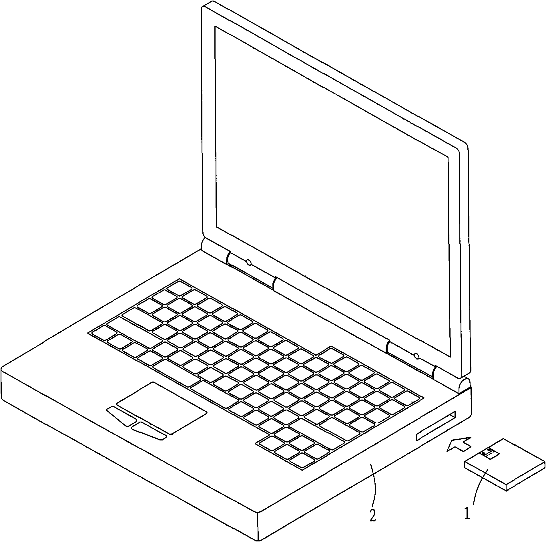
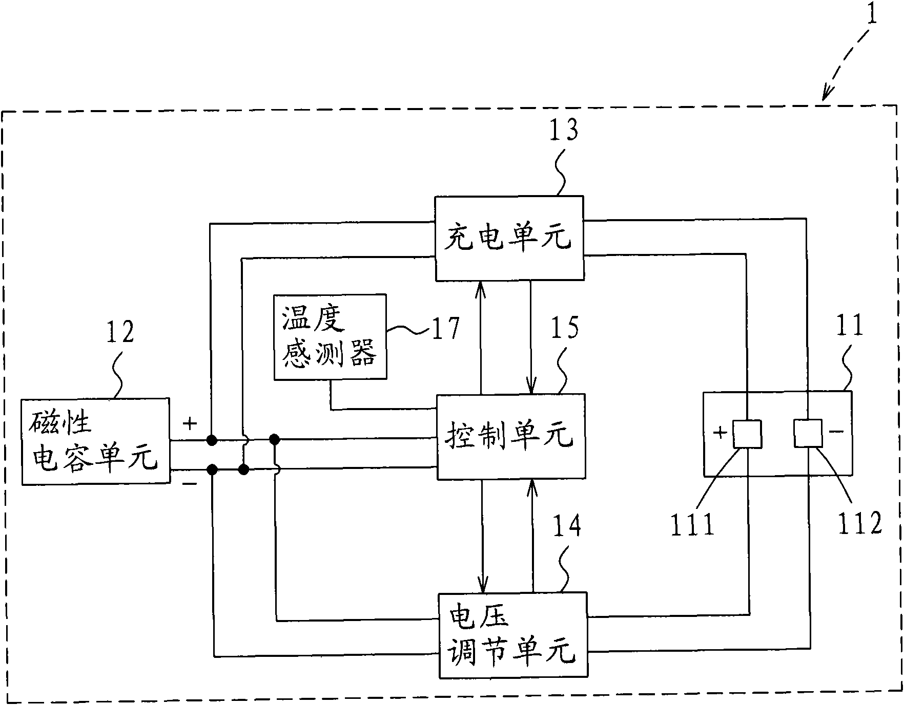
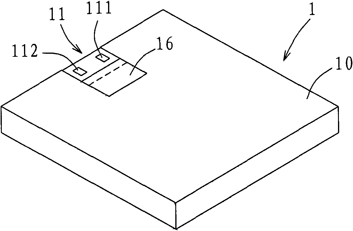
[0046] see figure 1 and figure 2 shown, figure 1 It is a three-dimensional schematic diagram of the appearance and use state of a preferred embodiment of the modularized energy storage device of the present invention, figure 2 It is a block diagram of the internal circuit of the modularized energy storage device of this preferr...


PUM


Abstract

The invention relates to a modularized energy storing device, which is designed for a magnetic capacitor energy storing card, and is provided with a magnetic capacitor unit arranged in a shell, a conducting connection interface electrically connected with the magnetic capacitor unit and exposed out of the shell, a charging unit electrically connected with the conducting connection interface, a voltage regulating unit electrically connected with the conducting connection interface, and a control unit which is electrically connected with the conducting connection interface, the charging unit and the voltage regulating unit and can timely control the charging unit to charge the magnetic capacitor unit according to a power signal input by the conducting connection interface or controls the voltage regulating unit to perform boost or buck conversion on the output voltage of the magnetic capacitor unit so as to output a certain voltage to the conducting connection interface. The modularized energy storing device has a standardized size and simultaneously has the advantages of long service life (high charge and discharge frequency), high energy storing density, instant high-power output, quick charge and discharge and the like.

Description

technical field [0001] The invention relates to a power storage device, in particular to a modularized energy storage device using a magnetic capacitor as an energy storage element. Background technique [0002] With the advancement of science and technology, at the same time, with the growing demand of consumers for small (thin) portable electronic devices with exquisite shapes, because portable electronic products are becoming more and more compact, the right choice to provide storage power The best battery is the key to the success of product development. In other words, the conditions for selecting a battery should take into account such as: size, voltage, energy density, temperature performance, power consumption rate, and charge and discharge times. [0003] Working time is one of the first considerations when designing a notebook computer. Due to the high operating temperature of the notebook computer, the fast processor speed and peripheral configurations such as CD...

Claims


Application Information

Patent Timeline
Patent Type & Authority Applications(China)
IPC IPC(8): H02J15/00H01G4/005H01G4/008H01G4/08H01G4/10
Inventor 许跃腾郑宇竣
Owner LITE ON TECH CORP
Why Eureka
Try Eureka