Lithium-ion power battery

A power battery, lithium ion technology, applied in secondary batteries, battery pack components, circuits, etc., can solve the problems of poor shock resistance and extrusion resistance, shortened cycle life, shortened cycle life, etc. The effect of strong extrusion ability, good shock resistance and extrusion resistance, and long cycle life

Active Publication Date: 2011-04-27
周金平
View PDF0 Cites 0 Cited by
  • Summary
  • Abstract
  • Description
  • Claims
  • Application Information

AI Technical Summary

Problems solved by technology

The current laminated lithium-ion power battery has the following defects: (1), poor shock resistance and extrusion resistance
Regardless of whether it is a round or square laminated battery pack and placed in the casing, because there is no fixation and support, the protection is poor, so the laminated battery cell is easy to move in the casing, the shock resistance and extrusion resistance are poor, and it is easy to cause lithium The damage of the ion power battery shortens its cycle life; (2), easy to expand, high safety risk
After the liquid injection and formation of the lithium-ion power battery, the expansion of the laminated cell material after absorbing the electrolyte and the gas generated by charging and formation will cause the lithium-ion power battery to expand. The pressure is uniform, and there will be serious bulges in the middle. Although the round shell does not produce serious bulges like the square shell, there is also the risk and possibility of bulges, and the bulges will increase the internal resistance of the bulge in the middle of the battery. Heat generation will further cause the electrolyte to evaporate, causing the capacity loss of the bulging part, and even lead to early attenuation of the capacity, thereby greatly shortening its cycle life, and even causing damage to the battery. In severe cases, there is a possibility of explosion, which brings unsafe hidden dangers

Method used


Image

  • Lithium-ion power battery
  • Lithium-ion power battery
  • Lithium-ion power battery

Examples


Embodiment Construction

[0037] The present invention will be described in further detail below in conjunction with the accompanying drawings and embodiments.

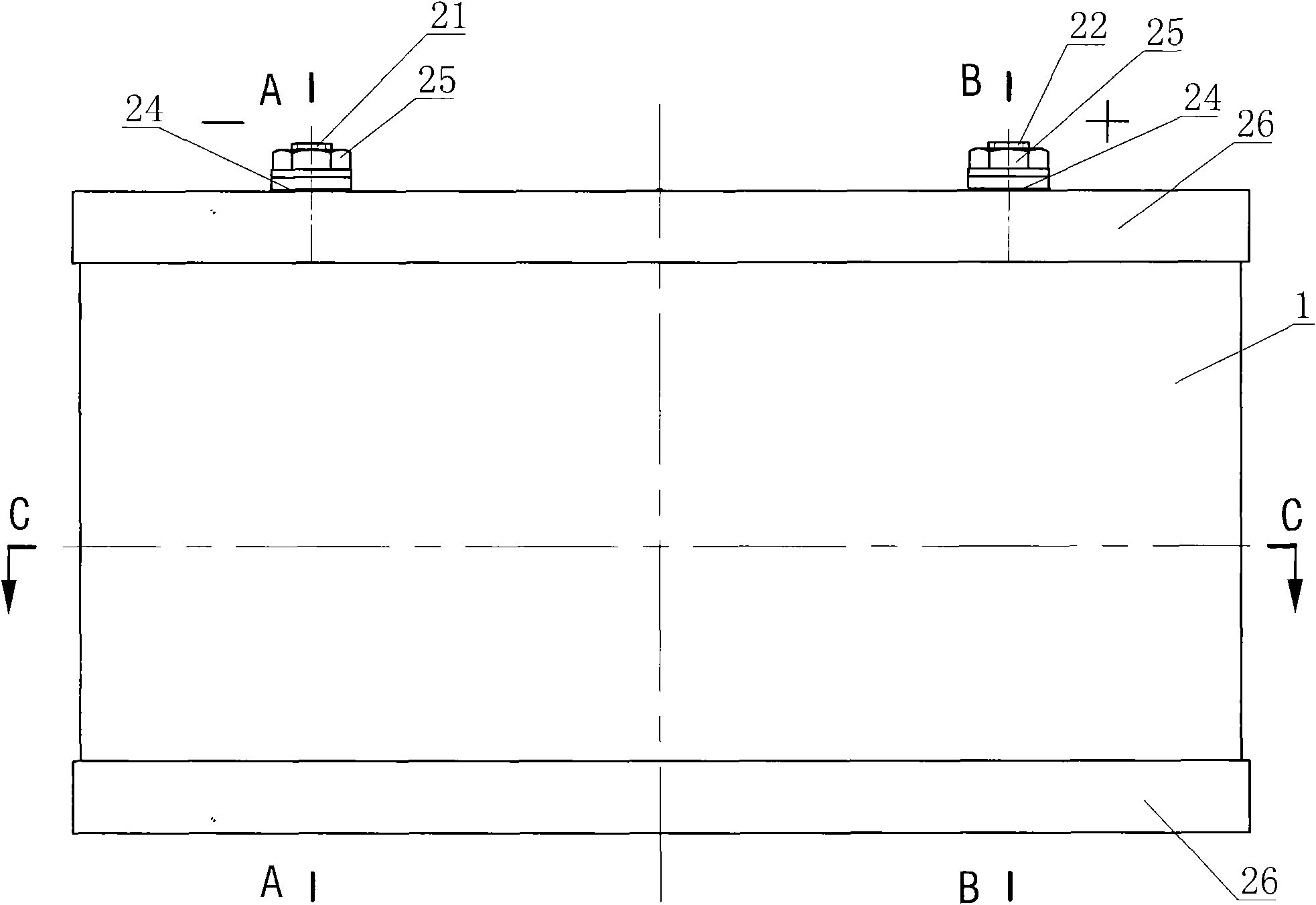
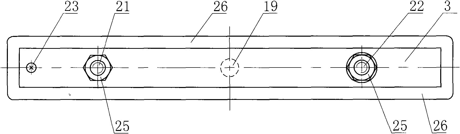
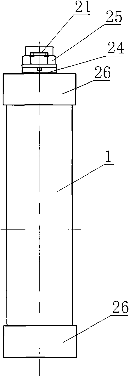
[0038] Such as Figure 1 to Figure 22As shown, a lithium-ion power battery includes a casing 1, an electronic mounting board 4 and a laminated cell 16, and also includes a negative tab joint 21 made of copper and a positive tab joint 22 made of aluminum, and also includes There is a positioning column 11 insulated from the negative electrode sheet 9, the positive electrode sheet 10, and the insulating diaphragm 7 of the laminated battery cell 16. The positioning column 11 is made of a core-piercing rivet, and the outer diameter of the middle of the core-piercing rivet is large and the outer diameter of the two ends is small. There are three positioning columns 11, including three insulating sleeves 12. The positioning column 11 is made of stainless steel, and also includes two side splints 5. Both the shell 1 and the side splints 5 are made of...


PUM


Abstract

The invention relates to a lithium-ion power battery, comprising a laminated battery cell (16). The laminated battery cell (16) comprises negative pole pieces (9), positive pole pieces (10) and insulating diaphragms (7), wherein, the negative pole pieces (9) and the positive pole pieces (10) are sequentially arrayed at intervals. The invention also comprises two side plywood (5) and positioning columns (11), wherein, the two side plywood (5) is used for clamping the negative pole pieces (9), the positive pole pieces (10) and the insulating diaphragms (7) and is provided with positioning holes(5-1); connecting holes (19) matching the positions of the positioning holes (5-1) are arranged on the insulating diaphragms (7), the negative pole pieces (9) and the positive pole pieces (10); the positioning columns (11) pass through the connecting holes (19) on the negative pole pieces (9), the positive pole pieces (10) and the insulating diaphragms (7) to be fixedly connected with the side plywood (5) at both ends in the positions of the positioning holes (5-1). The lithium-ion power battery has good capability of resisting shock and extrusion, is not easy to bulge and has long cycle life.

Description

technical field [0001] The invention relates to a rechargeable battery, in particular to a lithium-ion power battery, which belongs to the field of power batteries and is mainly used in various hybrid vehicles and pure electric vehicles using lithium-ion power batteries as power sources. Background technique [0002] At present, there are two main structures of lithium-ion power batteries. One is a rolled-type lithium-ion power battery in which the rolled batteries are packaged in a circular or square casing, but the heat dissipation of the batteries during the working process of this battery is only Relying on the gas convection exchange in the internal space and the heat conduction of a very small part of the medium, this structure cannot effectively solve the heat dissipation problem, which makes this structure unable to achieve a large capacity (only about 10Ah) lithium-ion power battery . Even if some manufacturers can increase the capacity, the battery capacity will q...

Claims


Application Information

Patent Timeline
Patent Type & Authority Patents(China)
IPC IPC(8): H01M10/36H01M10/38H01M2/10H01M2/12H01M50/24H01M50/242H01M50/264H01M50/289H01M50/342
CPCY02E60/12Y02E60/10Y02P70/50
Inventor 周金平
Owner 周金平
Why Eureka
Try Eureka