Flood discharging method for anticorrosion and energy dissipation of rotational flow ring dam and device thereof

A ring-shaped, energy-dissipating technology, applied in the direction of barrage/weir, water conservancy engineering, marine engineering, etc., can solve the problems of complex ventilation pipeline system, large fluctuation of water surface in the cave, damage to the ecological environment, etc., to protect the ecological environment and prevent corrosion. And the effect of good energy dissipation and less investment

Inactive Publication Date: 2010-02-03
CHINA INST OF WATER RESOURCES & HYDROPOWER RES
View PDF0 Cites 16 Cited by
  • Summary
  • Abstract
  • Description
  • Claims
  • Application Information

AI Technical Summary

Problems solved by technology

[0004] (2) There is generally a large negative pressure in the vertical shaft under the annular weir. In addition, the negative pressure at the top of the connection between the vertical shaft and the outlet tunnel is greater and prone to cavitation damage, and the flow velocity in the tunnel is high (total water head 100-200m, flow rate of 38-50m / s), it is also prone to cavitation damage, and at the exit of the cave, the jet flow of the cantilever is used to produce atomization, which will damage the ecological environment
[0006] (4) Although aeration facilities are installed in many places, there is also the possibility of cavitation damage on the bottom plate of the connection section with the water outlet tunnel (such as my country's Ertan 1 # spillway)
[0007] (5) The ventilation pipeline system is complex, which increases construction difficulties and is uneconomical
Many tests have proved that the increase of energy dissipation rate of this facility is very small (less than 2%), and the water level in the cave also fluctuates greatly.

Method used


Image

  • Flood discharging method for anticorrosion and energy dissipation of rotational flow ring dam and device thereof
  • Flood discharging method for anticorrosion and energy dissipation of rotational flow ring dam and device thereof
  • Flood discharging method for anticorrosion and energy dissipation of rotational flow ring dam and device thereof

Examples


Embodiment 1

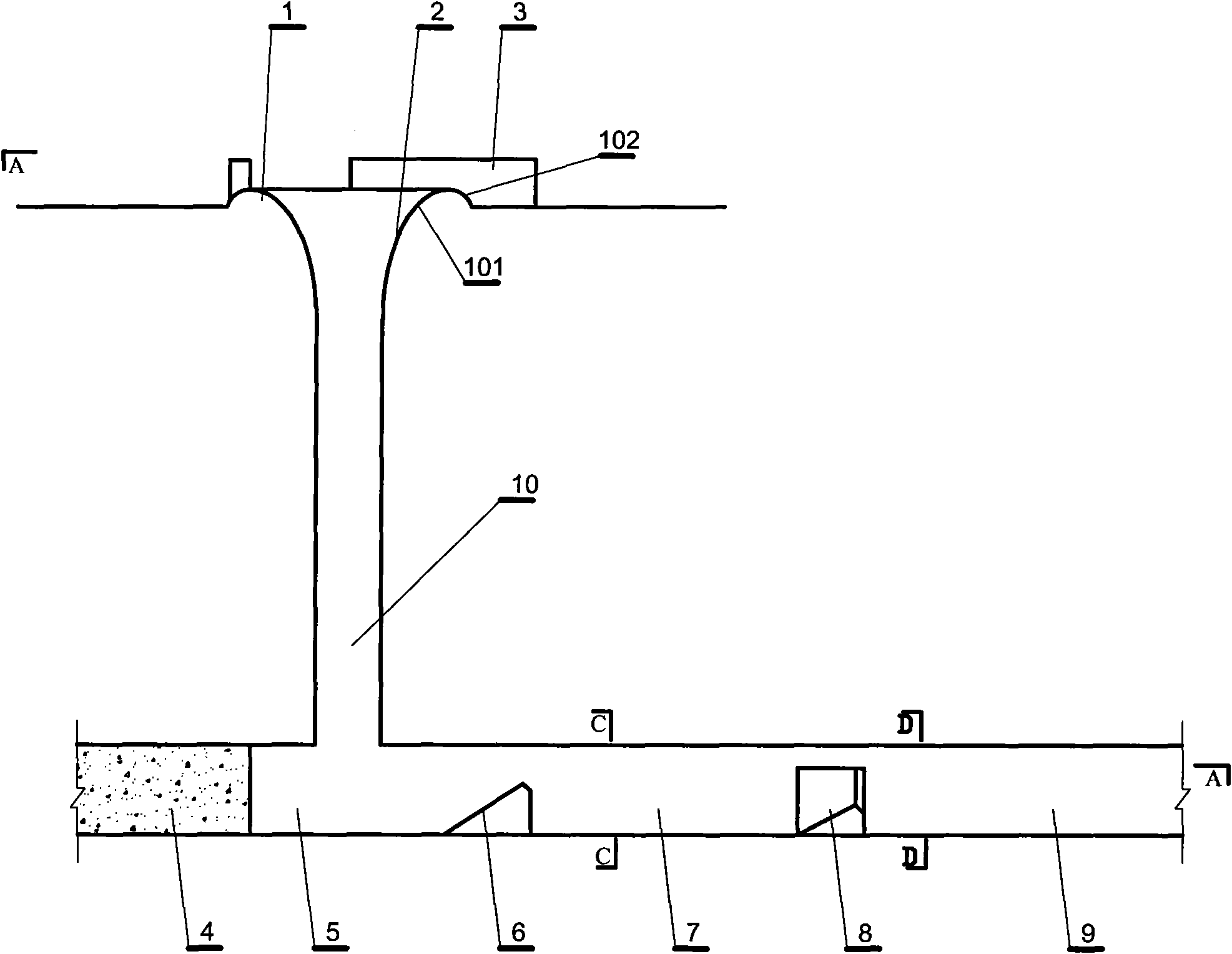
[0038] This embodiment is a flood discharge device for corrosion prevention and energy dissipation of a swirling annular weir, such as figure 1 , 4 shown. The device described in this embodiment includes: a shaft 10, the bottom of the shaft is connected to the horizontal energy dissipation tunnel, the energy dissipation tunnel is connected to the diversion tunnel 9, an annular weir 1 is arranged at the entrance of the shaft, and the inner ring of the annular weir Form a smooth constriction surface connection with the shaft to form a constriction 2. Several diversion piers 3 are arranged outside the annular weir, and the center line of the diversion piers and the tangent line of the annular weir form an included angle greater than or equal to 0° and less than 45°. There is a space 5 at the position where the vertical shaft connects with the energy dissipation tunnel and the position opposite to the energy dissipation tunnel, see figure 1 , 4 shown. The energy dissipation t...

Embodiment 2

[0054] This embodiment is an improvement of the first embodiment, and it is an improvement of the first embodiment about the diversion pier. The number of diversion piers described in this embodiment is 4-8.

[0055] Figure 4 Shown is the case of 4 diversion piers. Figure 5 is the case of five diversion piers. Image 6 is the case of eight diversion piers.

Embodiment 3

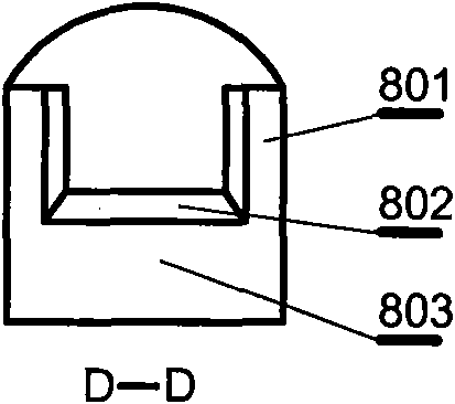
[0057] This embodiment is an improvement of the second embodiment, and is an improvement of the second embodiment on the diversion pier. The cross-sectional shape described in this embodiment is a rectangle 303 connected to a wedge 302, the wedge-shaped head 301 of the diversion pier from the proximal end of the annular weir is blunt and round, and the rectangular tail 304 of the diversion pier is circular, such as Figure 4 shown.

[0058] More precisely, the diversion pier should be a diversion wall, similar to a short wall. The cross-sectional shape of the short wall is rectangular. In order to improve the diversion effect, the head used in this embodiment is wedge-shaped, the angle of the wedge is relatively sharp, and the tip of the wedge transitions with a circular arc. In order to make the water flow smoothly, all the corners of the diversion piers use arc transitions.


PUM


Abstract

The invention relates to a flood discharging method for anticorrosion and energy dissipation of a rotational flow ring dam and a device thereof. The device comprises a vertical well; the bottom of thevertical well is communicated with a horizontal energy dissipation hole; the energy dissipation hole is communicated with a flow guide hole; the inlet of the vertical well is provided with the ring dam; the inner ring of the ring dam is connected with a smooth contracted curved surface formed in the vertical well; the ring dam is externally provided with a plurality of flow guide piers; the central lines of the flow guide piers and the tangent lines of the flow guide piers form inclined angles Theta which is larger than and equal to 0 degree and is less than 45 degree; a connection part between the vertical well and the energy dissipation hole, which is relative to the energy dissipation hole, is provided with a space; the energy dissipation hole is provided with a water collecting pier and a contracting pier; and a plunge pool is arranged between the water collecting pier and the contracting pier. Because the flow guide piers are tangent with the edge of the ring dam or the flow guide piers are connected with the edge of the ring dam by forming a small angle, the water flow is rotary, and spiral flow moves in the vertical well. The invention has simple structure, convenient construction, less investment, no maintenance, good anticorrosion and energy dissipation effect, no pulverization phenomenon at the outlet of the flood discharging hole, and protects ecology environment.

Description

technical field [0001] The invention relates to a flood discharge method and device for anti-corrosion and energy dissipation of a swirl annular weir, a method and a device for water conservancy flood control and discharge, and a method and device for anti-corrosion and energy dissipation in a flood discharge tunnel of a reservoir. Background technique [0002] The main purpose of building a dam is for flood control, power generation, urban water supply and agricultural irrigation, and the flood discharge structure is an important pivotal part to ensure the safety of the dam during the flood season. For a good drainage structure facility, it must meet the requirements of safe and reliable operation, low engineering investment and no damage to the downstream ecological environment. There are tens of thousands of large and medium-sized reservoirs in my country, most of which are earth-rock dams, and there are quite a few projects that fail to meet the flood control standards. ...

Claims


Application Information

Patent Timeline
Patent Type & Authority Applications(China)
IPC IPC(8): E02B8/06
Inventor 董兴林杨开林郭新蕾郭永鑫付辉王涛
Owner CHINA INST OF WATER RESOURCES & HYDROPOWER RES
Why Eureka
Try Eureka