Slide-block type reversing clutch

A clutch and slider type technology, which is applied in the field of slider type reversing clutches, can solve the problems that the machine cannot work, the balls are easy to wear and lose the roundness, and the balls are not easy to achieve. Effect

Inactive Publication Date: 2010-02-03
代绍康
View PDF0 Cites 4 Cited by
  • Summary
  • Abstract
  • Description
  • Claims
  • Application Information

AI Technical Summary

Problems solved by technology

Due to the small diameter of the ball itself, the contact surface between it and the outer ring is very small, and the ball is easy to wear out of round during the actual working process. When the roundness of the ball is reduced due to severe wear and fails, "clutch operation vibration noise" will appear. The phenomenon of "increasing" and "the ball is not easy to separate from the outer ring", and even a mechanical accident such as "the ball is stuck and the clutch is difficult" will occur in severe cases, making the machine unable to work

Method used


Image

  • Slide-block type reversing clutch
  • Slide-block type reversing clutch
  • Slide-block type reversing clutch

Examples


Embodiment 1

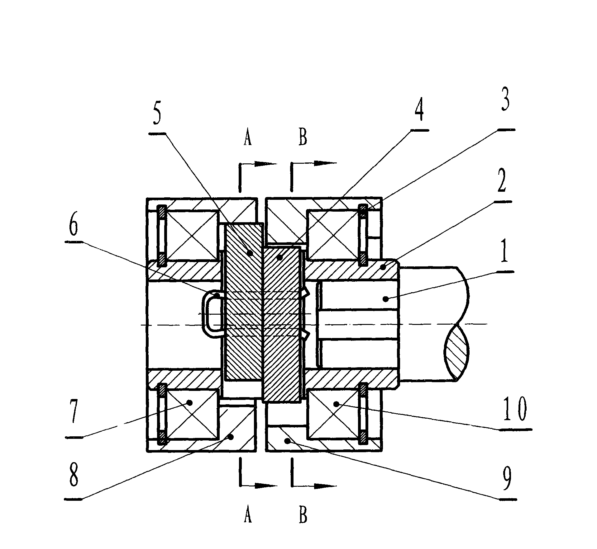
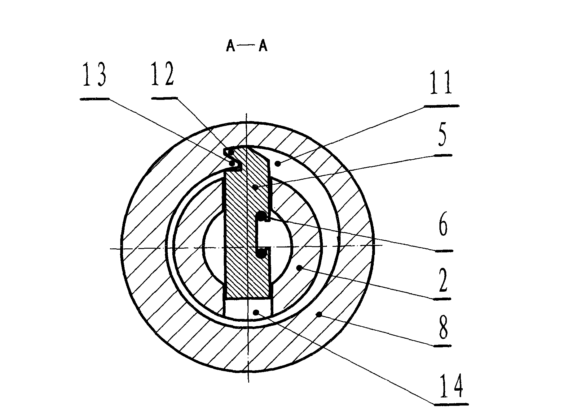
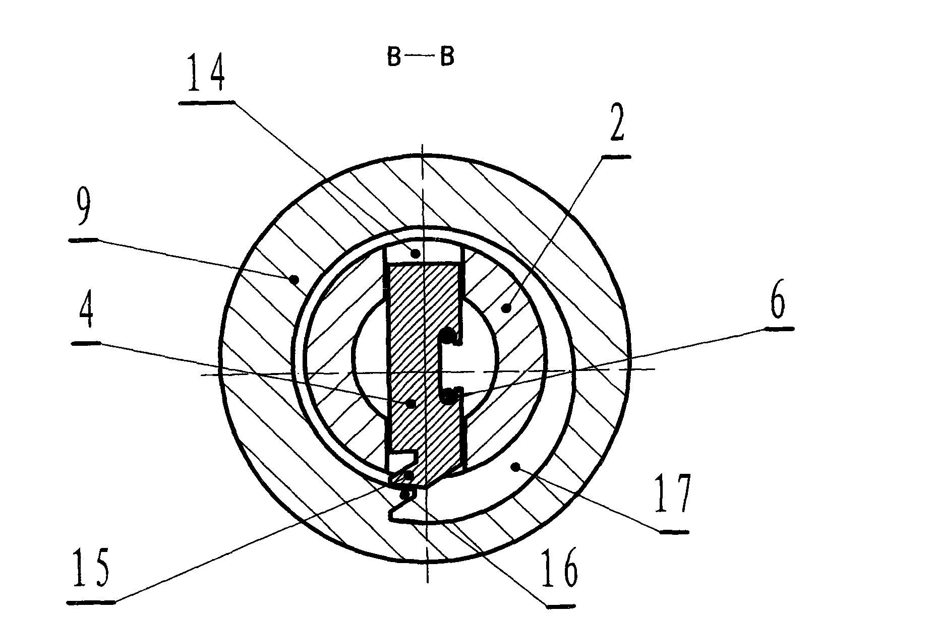
[0027] A slider-type reversing clutch with an inner sliding structure, which is mainly composed of a left pulley 8, a right pulley 9, bearings 7, 10, a shaft sleeve 2, and slider assemblies 5, 4, 6. The left pulley 8 , the right pulley 9 are respectively supported on the shaft sleeve 2 by bearings 7, 10, the bearings 7, 10 are axially positioned by the retaining ring 3, the shaft sleeve 2 is fixedly installed on the driving shaft 1 by the key 20, and the shaft sleeve 2 is made with a diameter To the through hole 14, the slider assembly 5, 4, 6 is slidingly fitted in the radial through hole 14 of the shaft sleeve 2, and the said slider assembly 5, 4, 6 is connected to the left slider by U-shaped spring 6 tension 5. The right slider 4 forms an integral structure. This structural design utilizes the elastic effect of the U-shaped spring 6 to play a good role in buffering and damping the left slider 5 and the right slider 4 when the reversing clutch moves. Effective reset effect, ...

Embodiment 2

[0029] A slider-type reversing clutch with an external sliding structure, which is implemented in the following manner: sliding slots 18, 19 are made on the slider assemblies 5, 4, 6, and the outer circle of the shaft sleeve 2 There is a section of flat square structure that is slidingly matched with the sliding long holes 18, 19, and the sliding long holes 18, 19 of the slider assembly 5, 4, 6 are slidably fitted on the flat side of the shaft sleeve 2 to form an external sliding type The reversing clutch structure enables the slider assembly 5, 4, 6 to slide on the flat side of the axle sleeve 2. And its other structures, working principles and working methods are the same as those described in the first embodiment. It can also well realize the purpose of using the driving shaft reversing to perform mechanical movement and power transmission clutch control proposed by the present invention.

Embodiment 3

[0031] A slider type reversing clutch is implemented in the following manner: said left drive wheel 8 and right drive wheel 9 are respectively made into a gear structure or a sprocket structure. And its other structures, principles and working methods are respectively the same as those described in Embodiment 1 or Embodiment 2. Can be respectively made into the sliding block type reversing clutch of internal sliding gear transmission or sprocket transmission and the sliding block type reversing clutch of external sliding gear transmission or sprocket transmission, all of which can realize the utilization of driving shaft reversing clutch proposed by the present invention. It has always been used for the purpose of mechanical movement and power transmission clutch control.


PUM


Abstract

The invention relates to a slide-block type reversing clutch mainly consisting of a left transmission wheel, a left transmission wheel, a bush and slide block components. The left transmission wheel and the right transmission wheel are supported on the bush by bearings. The slide block components are radially assembled on the bush in a sliding manner and positioned inside rims of the left transmission wheel and the right transmission wheel. Inner walls of the rims of the transmission wheels are provided with unidirectional progressive sliding grooves which can be form pallet tennon transmission fit by alternating with the slide block components. Only the change of the rotation direction of a driving shaft can realize transmission clutch switch so as to alternately drive the left transmission wheel or the right transmission wheel to rotate. The slide-block type reversing clutch can bear and transfer great power by using the slide block components as transmission clutch parts, and avoidthe phenomenon of transmission slip or seizure. The invention has the remarkable advantages of stable transmission fit, light and flexible reversing separation and no collision noise during clutchingoperation, can prolong the service life of the clutch by folds and has a good market prospect.

Description

Technical field: [0001] The invention relates to a mechanical clutch device, which belongs to the technical field of mechanical transmission automatic control, specifically a slider type reversing clutch, which is suitable for various types of existing mechanical equipment products, especially various small agricultural machinery products For supporting installation and use, the switching operation of reversing clutch is performed on mechanical movement and power transmission. Background technique: [0002] The machinery manufacturing industry is an important basic guarantee for the development of a country's national economy. According to relevant data, my country has become one of the major countries in the design, manufacture and use of mechanical equipment products in the world today. The traditional machinery industry has a long history of development. Modern machinery Industry has also made great achievements. my country has been able to design and manufacture various t...

Claims


Application Information

Patent Timeline
Patent Type & Authority Applications(China)
IPC IPC(8): F16D41/00
Inventor 代绍康
Owner 代绍康
Why Eureka
Try Eureka