Radio-frequency (RF) power supply device

A technology of radio frequency power supply and radio frequency signal, applied in the direction of circuits, electrical components, laser components, etc., can solve problems such as pollution, damage to laser performance, and reduce device life

Inactive Publication Date: 2010-02-03
HANS LASER TECH IND GRP CO LTD
View PDF0 Cites 23 Cited by
  • Summary
  • Abstract
  • Description
  • Claims
  • Application Information

AI Technical Summary

Problems solved by technology

The lubricating oil leaked from the Roots pump adheres the metal particles eroded after sputtering to the tube wall and optical lens of the resonant cavity, causing pollution, which not only destroys the performance of the laser, but also reduces the life of these devices

Method used


Image

  • Radio-frequency (RF) power supply device
  • Radio-frequency (RF) power supply device
  • Radio-frequency (RF) power supply device

Examples


Embodiment Construction

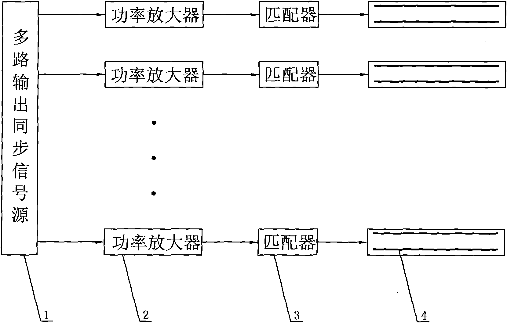
[0018] The present invention will be described in detail below in conjunction with the accompanying drawings and specific embodiments. Such as figure 1 Shown is a schematic diagram of the circuit structure of the radio frequency power supply device of the present invention. The radio frequency power supply device includes: a multi-channel output synchronous signal source 1 , a multi-channel power amplifier 2 , a multi-channel matcher 3 , and a multi-channel discharge electrode 4 .

[0019] Wherein, the multi-channel output synchronous signal source 1 is installed in a metal casing, and the multi-channel synchronous signal source 1 internally uses a quartz crystal oscillator to generate radio frequency oscillation, and uses a distributor to distribute the radio frequency oscillation signal and output it in multiple channels .

[0020] Wherein, the power amplifier 2 is installed in a metal casing with water cooling, the power amplifier 2 is a nonlinear amplifier, and the built-...


PUM


Abstract

The invention provides a radio-frequency (RF) power supply device provided with a multi-way output synchronizing signal source, power amplifiers, matchers and discharging electrodes. The output of each matcher is connected and matched with the discharging electrode; the input of each matcher is connected and matched with the output of the power amplifier; the outputs of the multi-way output synchronizing signal source are synchronously amplified by a plurality of ways of power amplifiers under the power supply action of a direct current power source; the RF discharge of a plurality of ways ofdischarging electrodes to gas is carried out under the joint action of a plurality of ways of matchers so that the gas in a plurality of ways of discharging electrodes generates glow. The gas producesplasma, generates laser in a laser resonant cavity and adopts a radio RF motivation mode; the RF electrodes are arranged outside the resonant cavity without contacting with the discharged gas; the RFis from 10 thousand to 3 million MHz; and ionization and discharge are carried out by the isolation of the gas in a glass motivation cavity so as to avoid polluting the resonant cavity and optical devices by the sputtering and the erosion of the electrodes.

Description

technical field [0001] The invention relates to a radio frequency power supply device. Background technique [0002] In terms of gas laser excitation, especially fast axial flow CO 2 Lasers are excited by DC discharges. CO in the cavity 2 Under the excitation of DC current, the molecule transitions from the ground state to the high energy level, forming the inversion of the number of particles, and then quickly falls to the low energy layer, and the emitted photons repeatedly oscillate between the front and rear window mirrors, and form the amplification of light after resonance, 50 % After being emitted from the front window mirror, a laser is formed. The electrodes of the DC electric field are all installed in the glass tube of the resonant cavity or at the joint, and are in direct contact with the discharge gas. After a short period of use, the resonant cavity and optical lens of the laser are contaminated by the coating of these metal particles, resulting in a decrea...

Claims


Application Information

Patent Timeline
Patent Type & Authority Applications(China)
IPC IPC(8): H01S3/0977
Inventor 高云峰叶建国谢根华张建群
Owner HANS LASER TECH IND GRP CO LTD
Why Eureka
Try Eureka